Kia Stinger CK: What to do in an emergency / Towing
Contents:
Towing service ➤
Removable towing hook
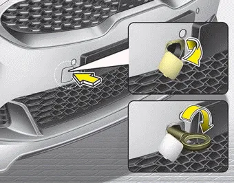
1. Open the liftgate, and remove the towing hook from the tool case.
2. Remove the hole cover pressing the right side part or lower part of the cover on the bumper.
3. Install the towing hook by turning it clockwise into the hole until it is fully secured.
4. Remove the towing hook and install the cover after use.
Emergency towing ➤


Other information:
Kia Stinger (CK) 2018-2023 Owner's Manual: Brake Line
Components and components location Components Repair procedures Removal 1. Turn ignition switch OFF and disconnect the negative (-) battery cable. 2. Remove the brake fluid from the master cylinder reservoir with a syringe. Do not spill brake fluid on the vehicle as it may damage the paint.Kia Stinger (CK) 2018-2023 Owner's Manual: Barometric Pressure Sensor (BPS)
Specifications Specification Item Specification Output Voltage (V) 5 Pressure (KPa) 32.5 - 284 Operating Voltage (V) 4.5 - 5.5 Pressure [kPa (kgf/cm², psi)] Output Voltage (Vref = 5V) 32.Categories
- Manuals Home
- Kia Stinger Owners Manual
- Kia Stinger Service Manual
- New on site
- Most important about car
Contents

Copyright © 2026 www.kstinger.com 0.0061