Kia Stinger CK: Rear Suspension System / Rear Shock Absorber
Components and components location
| Components |

| 1. Lock nut 2. Rear insulator 3. Bumper stopper |
4. Dust cover 5. Shock absorber |
Repair procedures
| Removal |
| 1. |
Remove wheel nuts, rear wheel and tire (A) from hub.
|


| 2. |
Loosen the rear shock absorber bolt & nut.
|

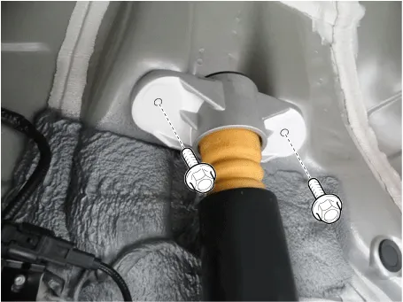
| 3. |
Loosen the rear shock absorber upper bolts and the remove the rear shock absorber.
|
| 4. |
Install in the reverse order of removal.
|
| Disassembly |
| 1. |
Using SST (09546-3X100), loosen the shock absorber lock nut (A).
|


| 2. |
Install in the reverse order of removal. |
| Inspection |
| 1. |
Check the rubber parts for wear and deterioration. |
| 2. |
Compress and extend the piston rod (A) and check that there is no abnormal resistance or unusual sound during operation.
|

Disposal
| 1. |
Fully extend the piston rod. |
| 2. |
Drill a hole on the (A) section to remove gas from the cylinder.
|


Other information:
Kia Stinger (CK) 2018-2023 Service Manual: Active hood sensor & unit assembly
Repair procedures Replacement 1. Disconnect the negative battery terminal. After disconnecting the cables, wait at least 30 seconds. 2. Remove the front bumper assembly. (Refer to Body - "Front Bumper Assembly") 3.*1 The system judges a person of adult size as an adult. When a smaller adult sits in the front passenger seat, the system may recognize him/her as a child depending on his/her physique and posture. *2 Do not allow children to ride in the front passenger seat. When a larger child who has outgrown a child restraint system sits in the front passenger seat, the system may recognize him/her as an adult depending upon his/her physique or sitting position.Categories
- Manuals Home
- Kia Stinger Owners Manual
- Kia Stinger Service Manual
- New on site
- Most important about car
