Kia Stinger CK: Engine Control System / Knock Sensor (KS)
Specifications
Item
|
Specification
|
Capacitance (pF)
|
850 - 1,150
|
Resistance (MΩ)
|
Approx. 1
|
Description and operation
Knocking is a phenomenon characterized by undesirable vibration and noise that
can cause engine damage. Knock Sensor (KS) is installed on the cylinder block and
senses engine knocking.
When knocking occurs, the vibration from the cylinder block is applied as pressure
to the piezoelectric element, and the sensor produces voltage signal to ECM. On
receipt of this signal, ECM will control the ignition timing by retarding the ignition
timing and then advancing the ignition timing when the knocking disappears. This
sequential control can improve engine power, torque and fuel economy.

Schematic diagrams
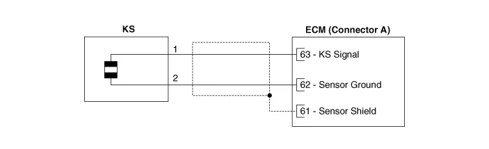
Harness Connector

Repair procedures
| 1. |
Switch "OFF" the ignition.
|
| 2. |
Disconnect the knock sensor connector.
|
| 3. |
Measure resistance between the injector terminals 1 and 2.
|
| 4. |
Check that the resistance is within the specification.
|
Specification: About 4.87 MΩ [20°C(68°F)]
|
|
| 1. |
Switch "OFF" the ignition and disconnect the negative (-) battery terminal.
|
| 2. |
Remove the intake manifold.
(Refer to Engine Mechanical System - “Intake Manifold”)
|
| 3. |
Remove the delivery pipe & injector assembly.
(Refer to Fuel Delivery System - "Delivery Pipe")
|
| 4. |
Remove the knock sensor (A) after loosening the mounting bolt from the
cylinder block.
|
Knock sensor installation bolt :
18.6 - 23.5 N·m (1.9 - 2.4 kgf·m, 13.7 - 17.4 lb·ft)
|

|
| • |
Install the component to the specified torques.
|
| • |
Note that internal damage may occur when the component is dropped.
If the component has been dropped, inspect before installing.
|
|
| 1. |
Install in the reverse order of removal.
|
Other information:
Kia Stinger (CK) 2018-2023 Service Manual: Audio Remote Control
Components and components location
Components
1. Left Remote Control Switch
(Audio + Bluetooth + Voice)
2. Right Remote Control Switch
(Trip Computer + ACC + SCC)
Schematic diagrams
Circuit Diagram
[Audio + Bluetooth + Voice]
[Trip + ACC]
[Trip + ACC + SCC]
Repair procedures
Removal
1.
Kia Stinger (CK) 2018-2023 Service Manual: Fluid
Repair procedures
Automatic Transmission Fluid
(ATF) Level Check
1.
Start the engine to warm up the ATF.
Do not step on the brake and accelerator simultaneously to warm
up the ATF.
2.


