Kia Stinger CK: Engine Control System / Rail Pressure Sensor (RPS)
Specifications
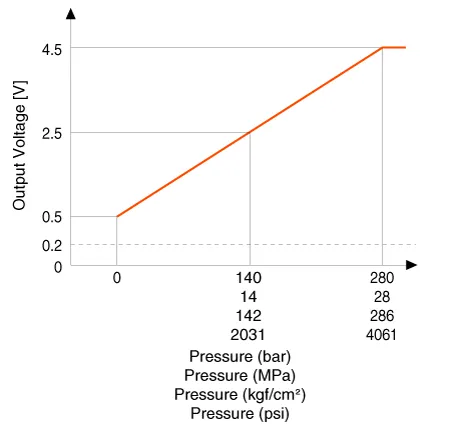
| Specification |
|
Pressure |
Output Voltage (V) [Vref=5V] |
|
|
bar |
[MPa (kgf/cm², psi)] |
|
|
0 |
0 (0, 0) |
0.5 |
|
140 |
14 (142, 2031) |
2.5 |
|
280 |
28 (286, 4061) |
4.5 |
Description and operation
| Description |
Installed on the delivery pipe, the Rail Pressure Sensor (RPS) measures the instantaneous fuel pressure in the delivery pipe. The sensing element (semiconductor element) built into the sensor converts the pressure to voltage signal. By using this signal, the ECM controls the correct injection amount and timing and adjusts the fuel pressure with the fuel pressure regulator valve if the actual pressure calculated by the RPS output signal is different from the target pressure.

Schematic diagrams
| Circuit Diagram |

| Harness Connector |

Repair procedures
| Inspection |
| 1. |
Connect the KDS on the Data Link Connector (DLC). |
| 2. |
Measure the output voltage and fuel pressure of the RPS at idle and various engine speed.
|
||||||||||||||

| Removal |
| 1. |
Release the residual pressure in fuel line. (Refer to the Fuel Delivery System - "Release Residual Pressure in Fuel Line") |
| 2. |
Switch "OFF" the ignition and disconnect the negative (-) battery terminal. |
| 3. |
Remove the intake manifold. (Refer to Engine Mechanical System - “Intake Manifold”) |
| 4. |
Remove the delivery pipe foam (A).
|

| 5. |
Disconnect the rail pressure sensor connector (A), and then remove the sensor (B) from the delivery pipe.
|

| Installation |
|

| 1. |
Install in the reverse order of removal. |
Troubleshooting
| Signal Waveform |


Other information:
Kia Stinger (CK) 2018-2023 Service Manual: Engine Control / Fuel System
Special service tools Special Service Tools Tool Name / Number Illustration Description Fuel Pressure Gauge 09353-24100 Used for measuring the pressure in fuel line Fuel Pressure Gauge Adaptor 0K353-D4100 Used for connecting between high pressure fuel pump and low pressure fuel feed tube to measure the pressure in fuel line ※SST 09353-02100 also can be used Heated Oxygen Sensor Socket Wrench 09392-1Y100 Removal and installation of the heated oxygen sensor ※ SST No.Service data Service Data Item Specification Product name Transfer case Operation method Electronic actuator control method (DC motor) Torque capacity 1,000 Nm Weight 24.8 kg (Oil injection state) Tightening torque Tightening Torques Item N·m Kgf·m lb·ft Bolt for fixing the transfer case 29.Categories
- Manuals Home
- Kia Stinger Owners Manual
- Kia Stinger Service Manual
- New on site
- Most important about car
