Kia Stinger CK: Engine Control System / Exhaust Gas Temperature Sensor (EGTS)
Specifications
| Specification |
Exhaust Gas Temperature Sensor (EGTS) #1, 2
▷ Type : Thermistor type
|
Temperature [°C (°F)] |
Resistance (kΩ) |
|
-40 (-40) |
0.17 |
|
0 (-32) |
0.201 |
|
100 (212) |
0.276 |
|
200 (392) |
0.35 |
|
300 (572) |
0.42 |
|
400 (752) |
0.489 |
|
500 (932) |
0.555 |
|
600 (1112) |
0.618 |
|
700 (1292) |
0.68 |
|
800 (1472) |
0.739 |
|
850 (1562) |
0.767 |
Description and operation
| Description |
Installed in exhaust manifold, the Exhaust Gas Temperature Sensor (EGTS) #1 for WGT senses the temperature of exhaust gas flowing into the WGT.
Installed in Gasoline Particulate Filter (GPF) assembly, the Exhaust Gas Temperature Sensor (EGTS) #2 for GPF senses the temperature of exhaust gas flowing into the GPF.
When predetermined engine condition is met, ECM burns soot collected in GPF with exhaust gas. During this, the exhaust gas temperature is an important factor of engine condition.
Schematic diagrams
| Circuit Diagram |
EGTS #1
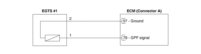
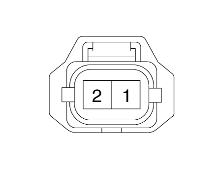
Harness Connector
EGTS #2
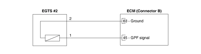
Harness Connector
EGTS #3
Repair procedures
| Inspection |
| 1. |
Turn ignition switch OFF. |
| 2. |
Disconnect the connector of exhaust gas temperature sensors #1/#2/#3. |
| 3. |
Measure resistance between sensor signal terminal and ground terminal. |
| 4. |
Check that the resistance is within the specification. Exhaust Gas Temperature Sensor [EGTS #1, #2, #3 (T3, T4, T5)]
|
| Removal & Installation |
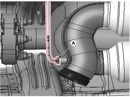
[EGTS #1]
| 1. |
Turn the ignition switch OFF and disconnect the battery negative (-) terminal. |
| 2. |
Remove the floor under cover. |
| 3. |
Disconnect the EGTS connector (A).
|
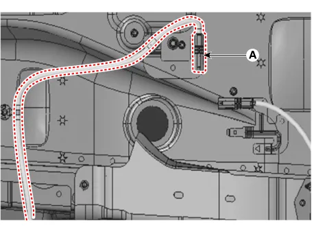
| 4. |
Remove the EGTS (A).
|
| 5. |
Install the sensor in the reverse order of removal.
|

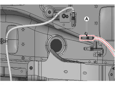
[EGTS #2]
| 1. |
Turn the ignition switch OFF and disconnect the battery negative (-) terminal. |
| 2. |
Remove the floor under cover. |
| 3. |
Disconnect the EGTS connector (A).
|
| 4. |
Remove the EGTS (A).
|
| 5. |
Install the sensor in the reverse order of removal.
|
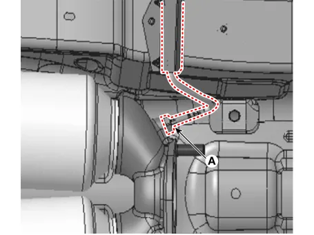
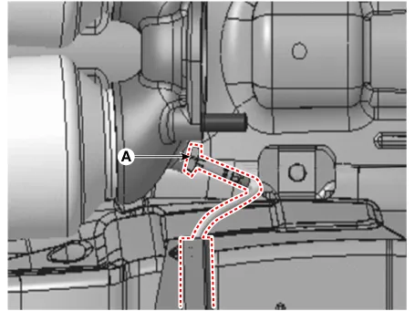
[EGTS #3]
| 1. |
Turn the ignition switch OFF and disconnect the battery negative (-) terminal. |
| 2. |
Remove the floor under cover. |
| 3. |
Disconnect the EGTS connector (A).
|

| 4. |
Remove the EGTS (A).
|
| 5. |
Install the sensor in the reverse order of removal.
|


Other information:
Kia Stinger (CK) 2018-2023 Service Manual: Steering Column & Shaft
Components and components location Components 1. Steering column module (SCM) 2. Steering column module (SCM) bracket Specifications Specification Item Specifications Rated Voltage DC 12 V Operating Voltage Range DC 9 - 16 V Operating Temperature Range -30°C ~ +75°C Storage Temperature Range -40°C ~ +85°C Dark Current Max.Kia Stinger (CK) 2018-2023 Service Manual: Engine Control / Fuel System
Special service tools Special Service Tools Tool Name / Number Illustration Description Fuel Pressure Gauge 09353-24100 Used for measuring the pressure in fuel line Fuel Pressure Gauge Adaptor 0K353-D4100 Used for connecting between high pressure fuel pump and low pressure fuel feed tube to measure the pressure in fuel line ※SST 09353-02100 also can be used Heated Oxygen Sensor Socket Wrench 09392-1Y100 Removal and installation of the heated oxygen sensor ※ SST No.Categories
- Manuals Home
- Kia Stinger Owners Manual
- Kia Stinger Service Manual
- New on site
- Most important about car
