Kia Stinger CK: Engine Control System / Injector
Specifications
Item
|
Specification
|
Coil Resistance (Ω)
|
1.4 - 1.6 [20°C(68°F)]
|
Description and operation
The GDI injector is similar to a standard injector, but sprays fuel at a much
higher pressure directly into the combustion chamber and has a swirl disc to get
the fuel swirling as it exits the nozzle. This aids in atomization of the fuel.
The ECM controls both the feed circuits (high side) to feed voltage to the injectors
and the ground circuits (low side) to energize the injectors. Also, the feed for
2 injectors comes from the same driver set. As the ignition coils are paired with
cylinders (1-4 and 2-3), the injectors are also set up in pairs.

Schematic diagrams

Harness Connector

Repair procedures
| 1. |
Switch "OFF" the ignition.
|
| 2. |
Disconnect the injector connector.
|
| 3. |
Measure resistance between the injector terminals 1 and 2.
|
| 4. |
Check that the resistance is within the specification.
|
Specification: 1.18 - 1.31 [20°C(68°F)]
|
|
| 1. |
Release the residual pressure in fuel line.
(Refer to the Fuel Delivery System - "Release Residual Pressure in Fuel
Line")
|
| 2. |
Switch "OFF" the ignition and disconnect the negative (-) battery terminal.
|
| 3. |
Remove the intake manifold.
(Refer to Engine Mechanical System - “Intake Manifold”)
|
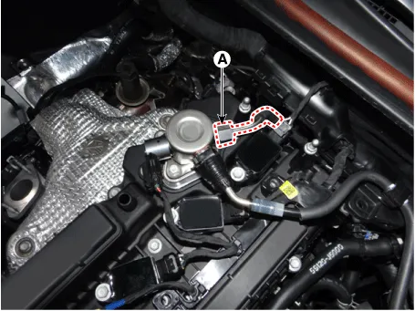
| 4. |
Remove the delivery pipe foam (A).

|
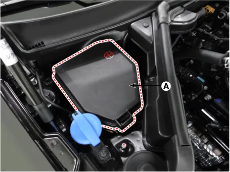
| 5. |
Remove the cowl top cover assembly.
(Refer to Body (Interior and Exterior) - Cowl Top Cover")
|
| 6. |
Remove the engine box cover (A).
|
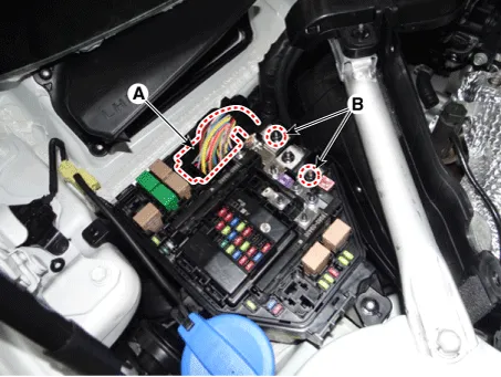
| 7. |
Disconnect the front control connector (A).
|
| 8. |
Remove the groune terminal nuts (B).
|
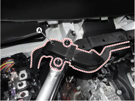
| 9. |
Remove the wiring protector (A).
|
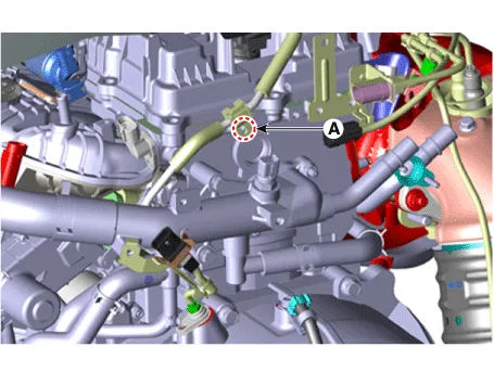
| 10. |
Remove the high pressure fuel pipe.
| (1) |
Remove the high pressure fuel pipe mounting bolt (A).
|
| (2) |
Remove the high pressure fuel pipe flange nut (A).
|
|
| 11. |
Remove the mounting bolts (A), and then remove the delivery pipe & injector
assembly from the engine.

|
| 12. |
Disconnect the injector & rail pressure sensor connector (A).
|
| 13. |
Remove the injector (B) from the delivery pipe.

|

| • |
Do not reuse injector fixing clips.
|
| • |
Install the component to the specified torques.
|
| • |
Note that internal damage may occur when the component is dropped.
If the component has been dropped, inspect before installing.
|
| • |
Apply engine oil to the injector O-ring.
|
| • |
Do not reuse injector O-rings.
|
| • |
When inserting the injector, be careful not to damage the injector
tip.
|
| • |
Do not reuse the high pressure fuel pipe.
|
|
| • |
Do not reuse the support disc.
|
| • |
Do not reuse the injector rubber washer.
|
| • |
When replacing the rubber washer, the steal plate (A) part should
be facing the cylinder installation part and the rubber plate (B)
part should be facing the injector body part.
|

|
| • |
Do not reuse the combustion seal.
|
|
| • |
When tightening the delivery pipe installation bolts, pre-tighten
them by hand, and then fully tighten them in the sequence of ② →
③ →① →④.
|

|
| 1. |
Install in the reverse order of removal.
|
The injector combustion seal should be replaced with a new one to prevent leakage
after removing the injector.
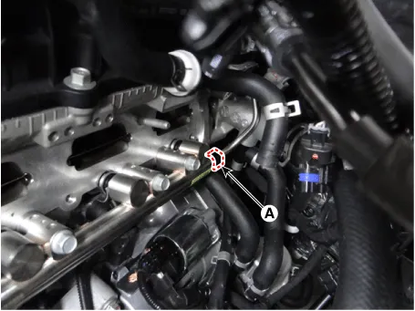
| 1. |
Remove the combustion seal (A) with a wire cutter.

|
With a wire cutter, carefully grab and pull out the sealing ring
into a small loop and then cut it out.
Be careful not to damage the surface of the valve sleeve with
the wire cutter.
|
|
| 2. |
Before reassembling the sealing ring, clean the groove with a clean cloth.
Any coking on the injector sealing surface must be carefully removed
with a brass-wire brush.

|
The surfaces of the new sealing ring must be clean and free of
grease.
|
|
| 3. |
Place the seal installing guide (B) (SST No.: 09353-2B000) on the tip
of the injector so as not to damage the injector tip (A).
Push the sealing ring (C) with thumb and index finger over the conical
assembly tool until it snaps into the groove.
The complete assembly must not take longer than 2 to 3 seconds.


|
| 4. |
To size the sealing ring the injector is first introduced into the sizing
tool (A) (SST No.: 09353-2B000) and then pressed and at the same time rotated
180° into the sizing tool.

|
| 5. |
Pull the injector out of the sizing tool by turning it in the reverse
direction of the press-in process.
|
Check that the seal ring has not been damaged during assembly
to the injector and that no circumferential scratches are present.
Do not reuse the combustion seal.
The seal must be completely free of grease and oil.
|
|
| 6. |
Check that the combustion seal (A) is correctly installed.

|
Troubleshooting
The three waveforms below are taken from the #1 and #4 injectors. The top waveform
is from the high side (feed side) of the #1 and #4 injectors, while the middle waveform
is from the low side (ground side) of the #1 injector and the bottom waveform is
from the low side of the #4 injector.
The middle waveform is the same as the top waveform because there is no ground
for the circuit. With no current flowing in the circuit, the #1 injector is not
energized and fuel does not flow.
The bottom waveform shows that ground is supplied and there is a voltage drop
across the #4 injector. With current flowing in the circuit, the #4 injector is
energized and fuel flows.

Other information:
Kia Stinger (CK) 2018-2023 Service Manual: Compressor
Components and components location
Component
[THETA Engine]
1. Clutch Bolt
2. Limiter Bolt
3. Limiter & Hub Assembly
4. Snap Ring
5. Pulley
6. Compressor Assembly
[LAMBDA Engine]
1. Clutch Bolt
2. Limiter Bolt
3. Limiter & Hub Assembly
4.
Kia Stinger (CK) 2018-2023 Service Manual: Rear Disc Brake
Components and components location
Components
[Standard]
1. Caliper housing
2. Brake member
3. Brake pad assembly [IN]
4. Retainer
5. Brake pad assembly [OUT]
6. Brake pad return spring
[Brembo]
1. Caliper housing
2. Brake pad
3. Brake pad
4.


