Kia Stinger CK: Engine Control System / Accelerator Position Sensor (APS)
Specifications
| Specification |
|
Accelerator Position |
Output Voltage (V) [Vref = 5V] |
|
|
APS1 |
APS2 |
|
|
C.T |
0.7 - 0.8 |
0.33 - 0.43 |
|
W.O.T |
3.99 - 4.23 |
1.94 - 2.18 |
Description and operation
| Description |
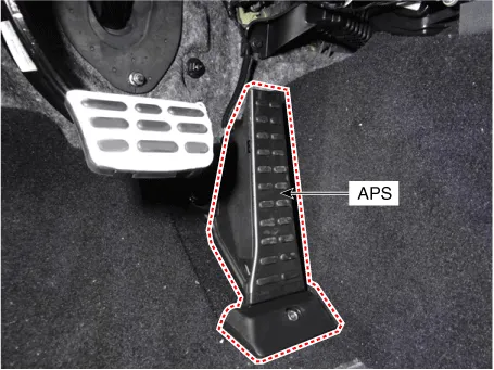
Installed on the accelerator pedal module, the Accelerator Position Sensor (APS) detects the rotation angle of the accelerator pedal. As the APS is one of the most important sensors in the engine control system, each of its two sensors has independent power and ground line. APS 2 monitors APS 1, and its output voltage is half that of APS 1. If the ratio of APS 1 and APS 2 is out of range (approximately 1/2), the diagnostic system judges it as abnormal.
Schematic diagrams
| Circuit Diagram |

Harness Connector

Repair procedures
| Inspection |
| 1. |
Connect the KDS on the Data Link Connector (DLC). |
| 2. |
TSwitch "ON" the ignition. |
| 3. |
Measure the output voltage of the APS 1 and 2 at C.T and W.O.T.
|
|||||||||||
| Removal |
| 1. |
Switch "OFF" the ignition and disconnect the negative (-) battery terminal. |
| 2. |
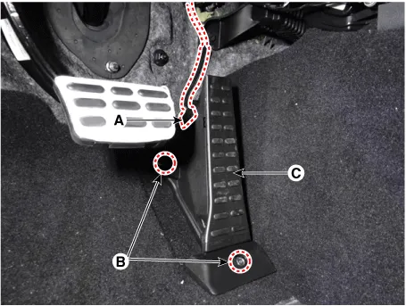
Disconnect the accelerator position sensor connector (A). |
| 3. |
Remove the accelerator position sensor (C) after loosening the mounting bolt and nut (B).
|
| Installation |
| 1. |
Install in the reverse order of removal. |


Other information:
Kia Stinger (CK) 2018-2023 Service Manual: Fluid (ATF)
Repair procedures Automatic Transmission Fluid (ATF) Level Check 1. Start the engine to warm up the ATF. Do not step on the brake and accelerator simultaneously to warm up the ATF. 2.Kia Stinger (CK) 2018-2023 Service Manual: Important safety precautions
You will find many safety precautions and recommendations throughout this section, and throughout this manual. The safety precautions in this section are among the most important. Always wear your seat belt A seat belt is your best protection in all types of accidents. Air bags are designed to supplement seat belts, not replace them. So even though your vehicle is equipped with air bags, ALWAYS make sure you and your passengers wear your seat belts, and wear them properly.Categories
- Manuals Home
- Kia Stinger Owners Manual
- Kia Stinger Service Manual
- New on site
- Most important about car
