Kia Stinger CK: Electric Power Steering / Steering Gear box
Components and components location
| Components |
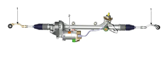
| 1. Tie rod end |
2. R-MDPS motor |
Repair procedures
| Removal |
| 1. |
Remove wheel nuts, front wheel and tire (A) from hub.
|


| 2. |
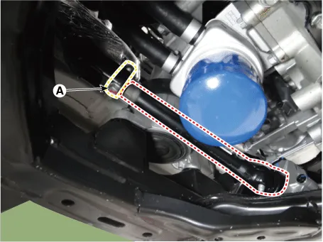
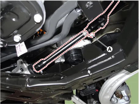
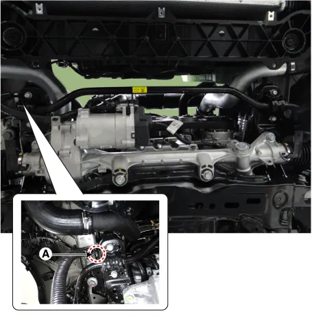
Loosen the bolt (A) and then separate the universal joint from the shaft joint.
[LHD]
[RHD]
|
| 3. |
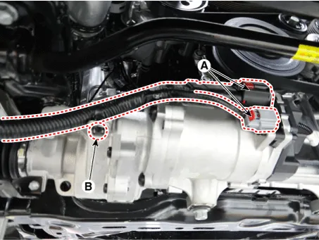
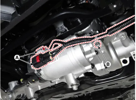
Disconnect the R-MDPS connector (A) and clip (B). [LHD]
[RHD]
|
| 4. |
Disconnect the R-MDPS wiring clip (A) from the sub frame.
|
| 5. |
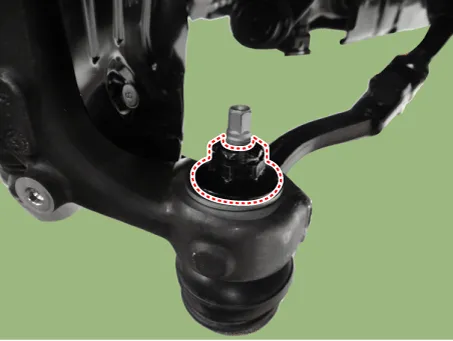
Remove the tie rod end nut.
|
| 6. |
Remove the knuckle by using the ball joint remover (A).
|
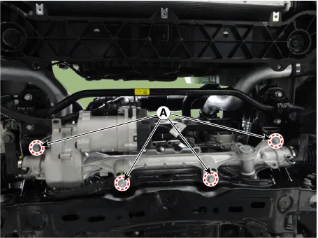
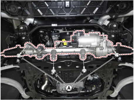
| 7. |
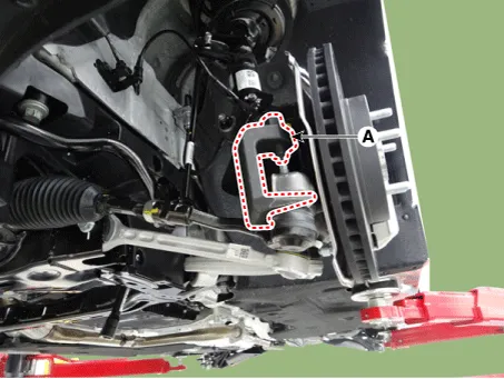
Loosen the gear box bolts (A) and then remove the gear box. [LHD]
[RHD]
|
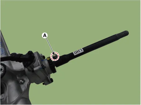
| 8. |
Loosen the shaft joint bolt (A) from the gear box.
|
| 9. |
Check the front alignment. (Refer to Suspension System - "Alignment") |
| 10. |
Install in the reverse order of removal. |
| 11. |
Register "ASP calibration EPS type recognition" by GDS after replacing steering column assembly. (Refer to Electric Power Steering - "Repair procedures") |


Other information:
Kia Stinger (CK) 2018-2023 Service Manual: Tail Gate Back Panel
Repair procedures Replacement • Use a plastic panel removal tool to remove interior trim pieces without marring the surface. • Take care not to bend or scratch the trim and panels. 1.Components and components location Components 1. Brake lamp switch 2. Brake pedal Description and operation Operation Operation principle of inductive non-contact switch 1. Use the high frequency magnetic field and the induced current that are generated by oscillation (to approved voltage) of coil in switch.Categories
- Manuals Home
- Kia Stinger Owners Manual
- Kia Stinger Service Manual
- New on site
- Most important about car
