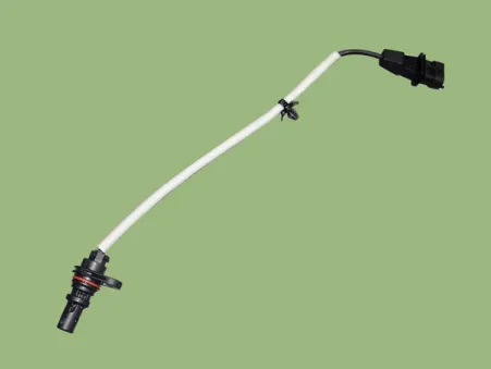
Kia Stinger CK: Engine Control System / Crankshaft Position Sensor (CKPS)
Specifications
Item
|
Specification
|
Type
|
Magnetic field sensitive
|
Output Voltage (V)
|
4.75 - 5.25 (25°C)
|
Input Voltage (V)
|
0.6 - 4.5
|
Air Cap (mm)
|
0.5 - 1.5
|
Description and operation
Crankshaft Position Sensor (CKPS) detects the crankshaft position and is one
of the most important sensors of the engine control system. Lack of CKPS signal
may cause the engine to stop. Installed on the cylinder block or the transaxle housing,
it generates alternating current by magnetic flux field made from the sensor and
the target wheel during engine runnig.
The target wheel consists of 58 slots and 2 missing slots on 360 degrees CA (Crank
Angle).
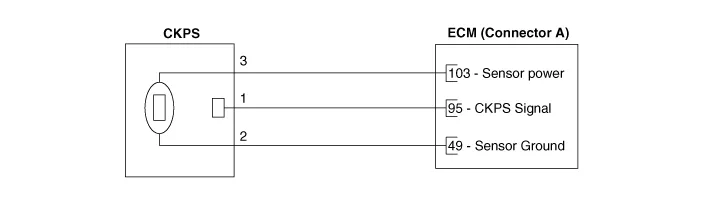
Schematic diagrams
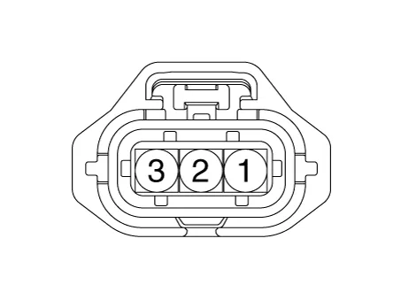
Harness Connector
Repair procedures
| 1. |
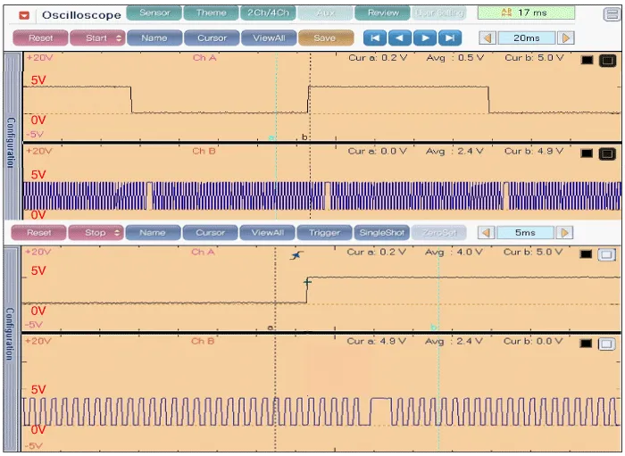
Check the signal waveform of the CMPS and CKPS using the KDS.
|
Specification: Refer to "Wave Form"
|
|
| 1. |
Switch "OFF" the ignition and disconnect the negative (-) battery terminal.
|
| 2. |
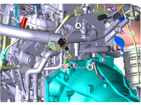
Disconnect the crankshaft position sensor connector (A).
|
| 3. |
Remove the installation bolt (A), and then remove the crankshaft position
sensor.
|
Crankshaft position sensor mounting bolt:
9.8 - 11.8 N·m (1.0 - 1.2 kgf·m, 7.2 - 8.7 lb·ft)
|
|
| • |
Install the component to the specified torques.
|
| • |
Note that internal damage may occur when the component is dropped.
If the component has been dropped, inspect before installing.
|
| • |
Apply the engine oil to the O-ring.
|
| • |
Insert the sensor in the installation hole and be careful not
to damage it.
|
|
| 1. |
Install in the reverse order of removal.
|
Troubleshooting