Kia Stinger CK: Engine Mechanical System / Cooling System
Kia Stinger (CK) 2018-2023 Service Manual / Engine Mechanical System / Cooling System
Contents:
- Coolant
- Cooling Fan
- Radiator
- Reservoir Tank
- Water Temperature Control Assembly
- Electric Thermostat (ECT)
- Water pump
Components and components location
| Components |
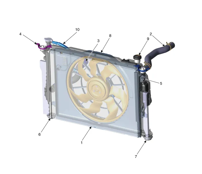
| 1. Radiator 2. Radiator upper hose 3. Radiator lower hose 4. Radiator upper mounting bracket (RH) 5. Radiator upper mounting bracket (LH) |
6. Radiator lower mounting insulator
(RH) 7. Radiator lower mounting insulator (LH) 8. Cooling fan assembly 9. Reservoir tank 10. Reservoir hose |
Troubleshooting
| Engine Overheat Troubleshooting |
|
Inspection |
Remedy |
||||||||
|
Visual inspection |
Inspect for shortage of coolant in reservoir tank . |
Reinspect after replenishing coolant. |
|||||||
Inspect for coolant pollution after removing radiator cap.
|
Reinspect after replacing coolant. |
||||||||
|
Inspect for leakage and loose coolant hoses (radiator hose, heater hose,
oil cooler hose, etc.). |
Reinspect for leakage after reinstalling hoses and clamps. |
||||||||
|
Inspect for leakage on water inlet fitting mounting part. |
Reinspect for leakage after replacing O-ring. |
||||||||
|
Reinspect for leakage after tightening to the specified torque. |
|||||||||
|
Inspect drive belt (for normal operation of water pump). |
Adjust drive belt tension or replace. |
||||||||
|
Inspect for leakage on water pump gasket mounting part. |
Reinspect for leakage after replacing gasket. |
||||||||
|
Reinspect for leakage after tightening to the specified torque. |
|||||||||
|
Inspect for loose coolant temperature sensor, cooling fan connector and
pin. |
Reinstall loose connector. |
||||||||
|
Replace relevant part if connector pin is damaged. |
|||||||||
|
Inspect operation status of cooling fan. - Check operation status by switching ON/OFF the heater control A/C.
|
Check mounting status of ground cable. |
||||||||
|
Diagnostic device |
Inspect self-diagnostic code using KDS/GDS. |
Check coolant temperature sensor, wiring, connector, etc. |
|||||||
|
Unit inspection |
Inspect water pump impeller. |
Replace water pump. |
|||||||
|
Inspect for foreign materials and status of thermostat valve. |
Inspect unit after removing foreign materials. |
||||||||
|
Inspect for stuck thermostat valve. - Immerse thermostat in water heated to over 95°C (203°F), then heat for at least 3 minutes to check valve lift.
|
Check valve lift. - Replace thermostat if valve lift is below specification or valve is stuck. |
||||||||


Coolant ➤
Cooling Fan ➤
Radiator ➤
Reservoir Tank
Repair procedures
| Removal |
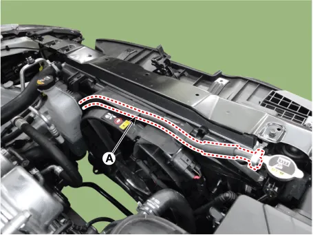
| 1. |
Disconnect the reservoir hose (A).
|
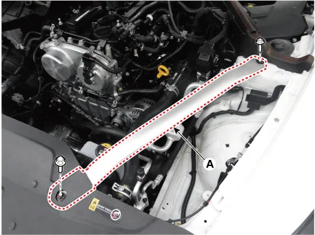
| 2. |
Remove the LH front strut bar (A).
|
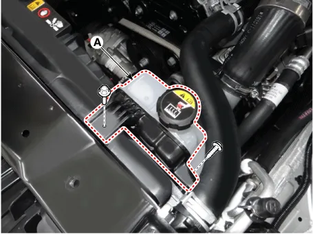
| 3. |
Remove the reservoir tank (A).
|
| 4. |
Install in the reverse order of removal. |
Water Temperature Control Assembly ➤
Electric Thermostat (ECT) ➤
Water pump ➤


Other information:
Kia Stinger (CK) 2018-2023 Service Manual: Drive mode integrated control system
The drive mode may be selected according to the driver's preference or road condition. The mode changes whenever the DRIVE MODE button is turned. SMART mode : SMART mode automatically adjusts the driving mode (ECO ↔ COMFORT ↔ SPORT) in accordance with the driver's driving habits. COMFORT mode : COMFORT mode provides smooth driving and a comfortable ride.Kia Stinger (CK) 2018-2023 Service Manual: Side Impact Sensor (SIS)
Description and operation Description • Side Impact Sensor (SIS) system consists of two Pressure Side Impact Sensor (P-SIS) installed at each center of the front door module (LH and RH), two SIS installed at each center pillar nearby (LH and RH) and two rear SIS installed in the rear pillar (LH and RH). • Pressure Side Impact Sensor is also called P-SIS because it detects pressure from collision at its mounting location.Categories
- Manuals Home
- Kia Stinger Owners Manual
- Kia Stinger Service Manual
- Coolant
- Cooling Fan
- Radiator
- Reservoir Tank
- Water Temperature Control Assembly
- Electric Thermostat (ECT)
- Water pump
- New on site
- Most important about car
Contents

Copyright © 2026 www.kstinger.com 0.0113