Kia Stinger CK: Cooling System / Water pump
Components and components location
| Components |
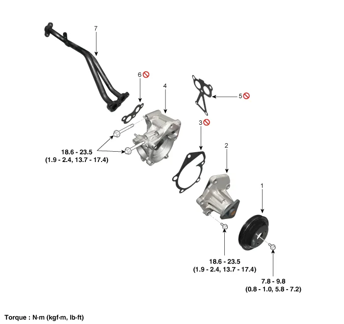
| 1. Water pump pulley 2. Water pump sub assembly 3. Water pump gasket 4. Water pump housing |
5. Water pump housing gasket
6. Water inlet pipe gasket 7. Heater & bypass pipe |
Repair procedures
| Removal and Installation |
| 1. |
Remove the engine room front under cover. (Refer to Engine and Transmission Assembly - "Engine Room Under Cover") |
| 2. |
Drain the coolant. (Refer to Cooling System - "Coolant") |
| 3. |
Remove the water pump belt. (Refer to Drive Belt System - "Drive Belt") |
| 4. |
Remove the electric thermostat (ECT). (Refer to Cooling System - "Electric Thermostat (ECT)") |
| 5. |
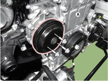
Remove the water pump pulley (A).
|
| 6. |
Remove the water pump sub assembly (A) with gasket.
|
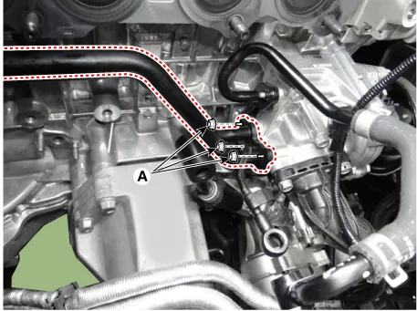
| 7. |
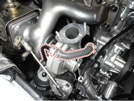
Disconnect the turbocharger water feed hose (A).
|
| 8. |
Remove the heater & bypass pipe mounting nuts (A).
|
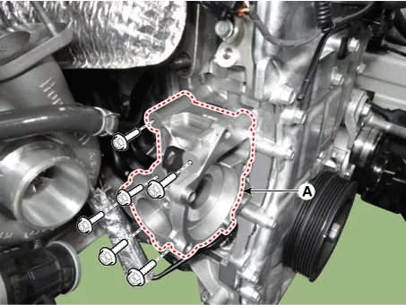
| 9. |
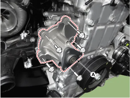
Remove the water pump housing (A) with gasket.
|
| 10. |
Disconnect the heater hoses (A).
|
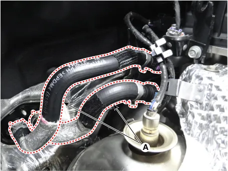
| 11. |
Disconnect the bypass hose (A).
|
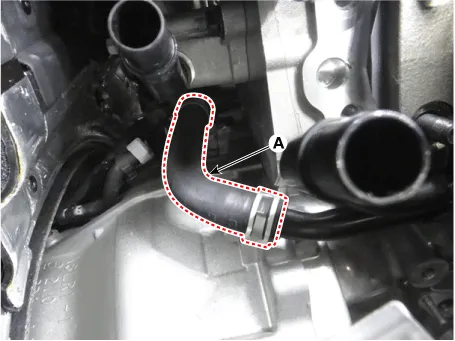
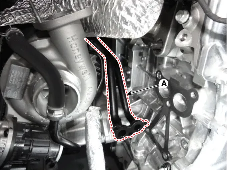
| 12. |
Remove the heater & bypass pipe (A).
|
| 13. |
Install the other parts in the reverse order of removal. |
| 14. |
Fill the coolant. (Refer to Cooling system - "Coolant") |
| 15. |
Start engine and check for leaks. |
| 16. |
Recheck engine coolant level. |
| Inspection |
| 1. |
Check each part for cracks, damage or wear, and replace the coolant pump assembly if necessary. |
| 2. |
Check the bearing for damage, abnormal noise and sluggish rotation, and replace the coolant pump assembly if necessary. |
| 3. |
Check for coolant leakage. If coolant leaks from hole, the seal is defective. Replace the coolant pump assembly.
|

Troubleshooting
| Troubleshooting |
|
Symptoms |
Possible Causes |
Remedy |
||||||||||||
|
Coolant leakage |
|
Visually check |
|
|
||||||||||
|
||||||||||||||
|
|
|
||||||||||||
|
|
|||||||||||||
|
|
|
||||||||||||
|
Noise |
|
Inspection with a stethoscope |
|
|
||||||||||
|
||||||||||||||
|
Inspection after removing a drive belt |
|
|
||||||||||||
|
||||||||||||||
|
Inspection after removing a water pump |
|
|
||||||||||||
|
Overheating |
|
Loosened impeller |
|
|
||||||||||
|
|
|||||||||||||


Other information:
Kia Stinger (CK) 2018-2023 Service Manual: ECS(Electronic Control Suspension) System
Components and components location Components 1. ECS ECU 2. Front ECS Damper 3. Wheel speed sensor 4. Rear ECS Damper 5. Body G Sensor Description and operation Operation System Check the MCU and the state of each part when electric power is applied to ECU and prepare to operate.Kia Stinger (CK) 2018-2023 Service Manual: Wireless Power Charging (WPC) Unit
Components and positions Components Circuit diagram Circuit Diagram Repair procedures Removal • Handling wireless charging system parts by wet hands may cause electric shock. • Put on gloves to protect your hands.Categories
- Manuals Home
- Kia Stinger Owners Manual
- Kia Stinger Service Manual
- New on site
- Most important about car
