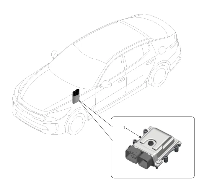
The module receives and processes signals from various sensors and implements
a wide range of transmission controls to ensure optimal driving conditions for the
driver.
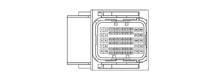
Pin
|
Description
|
Pin
|
Description
|
1
|
Underdrive Clutch control solenoid valve
|
40
|
Back UP Comm. (TCM→Electronic shift lever)
|
2
|
Damper clutch control solenoid valve
|
43
|
CAN HIGH
|
3
|
27 Brake control solenoid valve
|
44
|
CCP CAN LOW
|
5
|
6 Clutch control solenoid valve
|
45
|
D position solenoid valve (ON/OFF)
|
7
|
Line pressure control solenoid valve
|
49
|
Parking switch ground
|
8
|
35R Clutch control solenoid valve
|
52
|
CAN LOW
|
9
|
4&OD Clutch control solenoid valve
|
53
|
CCP CAN HIGH
|
10
|
8LR Brake control solenoid valve
|
54
|
P position solenoid valve (ON/OFF)
|
12
|
Back UP Comm. (TCM→Electronic shift lever)
|
55
|
Reverse lamp relay
|
14
|
Parking switch signal "S2" (PWM)
|
56
|
Output speed sensor (power), 9V
|
15
|
Parking switch power (5V)
|
58
|
Input speed sensor (power), 9V
|
18
|
R position solenoid valve (ON/OFF)
|
65
|
Solenoid valve power 1 (UD, 27, 8LR, DC)
|
20
|
Paddle shift (Down)
|
66
|
Solenoid valve power 2 (4&OD, 35R, 6C, LP)
|
21
|
Paddle shift (Up)
|
67
|
Power (VB)
|
22
|
Parking switch sinal "S1" (PWM)
|
68
|
Power (VB)
|
24
|
P/N relay
|
70
|
Solenoid valve power 3 (ON/OFF)
|
25
|
Oil temperature sensor (+)
|
71
|
Ground
|
26
|
Oil temperature sensor (-)
|
72
|
Solenoid valve power 4 (ON/OFF)
|
27
|
Back UP Comm. (TCM→Electronic shift lever)
|
73
|
Ground
|
31
|
Input speed sensor signal
|
74
|
Ground
|
32
|
Output speed sensor signal
|
-
|
-
|
Pin
|
Description
|
Pin
|
Description
|
1
|
Underdrive Clutch control solenoid valve
|
26
|
Oil temperature sensor (-)
|
2
|
Damper clutch control solenoid valve
|
31
|
Input speed sensor signal
|
3
|
27 Brake control solenoid valve
|
32
|
Output speed sensor signal
|
5
|
6 Clutch control solenoid valve
|
43
|
CAN HIGH
|
7
|
Line pressure control solenoid valve
|
44
|
CCP CAN LOW
|
8
|
35R Clutch control solenoid valve
|
49
|
Inhibitor switch ground
|
9
|
4&OD Clutch control solenoid valve
|
52
|
CAN LOW
|
10
|
8LR Brake control solenoid valve
|
53
|
CCP CAN HIGH
|
11
|
Manual mode switch "Select"
|
55
|
Reverse lamp relay
|
12
|
Manual mode switch "Up"
|
56
|
Output speed sensor (power), 9V
|
13
|
Manual mode switch "Down"
|
58
|
Input speed sensor (power), 9V
|
14
|
Inhibitor switch signal "S2"
|
65
|
Solenoid valve power 1 (UD, 27, 8LR, DC)
|
15
|
Inhibitor switch power (5V)
|
66
|
Solenoid valve power 2 (4&OD, 35R, 6C, LP)
|
18
|
SS-A solenoid valve (ON/OFF)
|
67
|
Power (VB)
|
20
|
Paddle shift (Down)
|
68
|
Power (VB)
|
21
|
Paddle shift (Up)
|
71
|
Ground
|
22
|
Parking switch sinal "S1" (PWM)
|
72
|
Solenoid valve power 4 (ON/OFF)
|
24
|
P/N relay
|
73
|
Ground
|
25
|
Oil temperature sensor (+)
|
74
|
Ground
|
Pin
|
Description
|
Condition
|
Input/Output Value
|
Type
|
Level
|
1
|
Underdrive clutch control solenoid valve
|
-
|
Output
|
0V/Battery voltage level
|
9V < Battery voltage level <16V
|
2
|
Damper clutch control solenoid valve
|
-
|
Output
|
0V/Battery voltage level
|
9V < Battery voltage level <16V
|
3
|
27 Brake control solenoid valve
|
-
|
Output
|
0V/Battery voltage level
|
9V < Battery voltage level <16V
|
5
|
6 Speed clutch control solenoid valve
|
-
|
Output
|
0V/Battery voltage level
|
9V < Battery voltage level <16V
|
7
|
Line pressure control solenoid valve
|
-
|
Output
|
0V/Battery voltage level
|
9V < Battery voltage level <16V
|
8
|
35R Clutch control solenoid valve
|
-
|
Output
|
0V/Battery voltage level
|
9V < Battery voltage level <16V
|
9
|
4&OD Clutch control solenoid valve
|
-
|
Output
|
0V/Battery voltage level
|
9V < Battery voltage level <16V
|
10
|
8LR Brake control solenoid valve
|
-
|
Output
|
0V/Battery voltage level
|
9V < Battery voltage level <16V
|
14
|
Parking switch signal S2
|
High
|
Input
|
0V/4.5 - 5.5 V
|
Low
|
4.5 < Battery voltage level < 5.5V
|
15
|
Parking switch power (5V)
|
High
|
Input
|
0V/4.5 - 5.5 V
|
Low
|
4.5 < Battery voltage level < 5.5V
|
18
|
R position solenoid valve (ON/OFF)
|
-
|
Output
|
0V/Battery voltage level
|
9V < Battery voltage level <16V
|
20
|
Paddle shift "Down"
|
Down ON
|
Input
|
0V/Battery voltage level
|
Other ON
|
|
9V < Battery voltage level < 16V
|
21
|
Paddle shift "Up"
|
UP
|
Input
|
0V/Battery voltage level
|
Other ON
|
9V < Battery voltage level < 16V
|
22
|
Parking switch signal S1
|
High
|
Input
|
0V / 4.5 - 5.5 V
|
Low
|
4.5 < Battery voltage level < 5.5V
|
24
|
P/N relay
|
ON
|
Output
|
About 1V
|
OFF
|
Battery voltage level
|
25
|
Oil temperature sensor (+)
|
-
|
Input
|
Maximum 5V voltage level
|
26
|
Oil temperature sensor (-)
|
-
|
Input
|
Minimum 0V voltage level
|
31
|
Input speed sensor signal
|
-
|
Pulse Input
|
Low : About 0.7V, High : 1.4V
|
Maximum/ Minimum Frequency :
|
9kHz/0Hz
|
32
|
Output speed sensor signal
|
-
|
Pulse Input
|
Low : About 0.7V, High : 1.4V
|
Maximum/ Minimum Frequency :
|
9kHz/0Hz
|
45
|
D position solenoid valve (ON/OFF)
|
-
|
Output
|
0V/Battery voltage level
|
9V < Battery voltage level <16V
|
54
|
P position solenoid valve (ON/OFF)
|
-
|
Output
|
0V/Battery voltage level
|
9V < Battery voltage level <16V
|
55
|
Reserve lamp relay
|
ON
|
Output
|
0V/Battery voltage level
|
OFF
|
56
|
Output speed sensor power
|
ON
|
Output
|
About 9V voltage level
|
OFF
|
0V
|
58
|
Input speed sensor power
|
ON
|
Output
|
About 9V voltage level
|
OFF
|
0V
|
65
|
Solenoid supply power 1
|
-
|
Power
|
Battery voltage level
|
(UD/C, 27/B, 8LR/B, D/C)
|
9V < Battery voltage level <16V
|
66
|
Solenoid supply power 2
|
-
|
Power
|
Battery voltage level
|
(4&OD/C, 35R/C, 6/C, L/P)
|
9V < Battery voltage level <16V
|
67
|
Battery power
|
ON
|
Power
|
0V/Battery voltage level
|
OFF
|
9V < Battery voltage level <16V
|
68
|
Battery power
|
ON
|
Power
|
0V/Battery voltage level
|
OFF
|
9V < Battery voltage level <16V
|
70
|
Solenoid supply power 3
|
-
|
Power
|
Battery voltage level
|
(ON/OFF solenoid)
|
9V < Battery voltage level <16V
|
71
|
Ground
|
-
|
Ground
|
0V (GND level)
|
72
|
Solenoid supply power 4
|
-
|
Power
|
Battery voltage level
|
(ON/OFF solenoid)
|
9V < Battery voltage level <16V
|
73
|
Ground
|
-
|
Ground
|
0V (GND level)
|
74
|
Ground
|
-
|
Ground
|
0V (GND level)
|
Pin
|
Description
|
Condition
|
Input/Output Value
|
Type
|
Level
|
1
|
Underdrive clutch control solenoid valve
|
-
|
Output
|
0V/Battery voltage level
|
9V < Battery voltage level <16V
|
2
|
Damper clutch control solenoid valve
|
-
|
Output
|
0V/Battery voltage level
|
9V < Battery voltage level <16V
|
3
|
27 Brake control solenoid valve
|
-
|
Output
|
0V/Battery voltage level
|
9V < Battery voltage level <16V
|
5
|
6 Speed clutch control solenoid valve
|
-
|
Output
|
0V/Battery voltage level
|
9V < Battery voltage level <16V
|
7
|
Line pressure control solenoid valve
|
-
|
Output
|
0V/Battery voltage level
|
9V < Battery voltage level <16V
|
8
|
35R Clutch control solenoid valve
|
-
|
Output
|
0V/Battery voltage level
|
9V < Battery voltage level <16V
|
9
|
4&OD Clutch control solenoid valve
|
-
|
Output
|
0V/Battery voltage level
|
9V < Battery voltage level <16V
|
10
|
8LR Brake control solenoid valve
|
-
|
Output
|
0V/Battery voltage level
|
9V < Battery voltage level <16V
|
11
|
Manual mode "Select"
|
Select
|
Input
|
0V/Battery voltage level
|
Other ON
|
9V < Battery voltage level < 16V
|
12
|
Manual mode "Up"
|
UP
|
Input
|
0V/Battery voltage level
|
Other ON
|
9V < Battery voltage level < 16V
|
13
|
Manual mode "Down"
|
Down
|
Input
|
0V/Battery voltage level
|
Other ON
|
9V < Battery voltage level < 16V
|
14
|
Inhibitor switch signal S2
|
High
|
Input
|
0V/4.5 - 5.5 V
|
Low
|
4.5 < Battery voltage level < 5.5V
|
15
|
Inhibitor switch power (5V)
|
High
|
Input
|
0V/4.5 - 5.5 V
|
Low
|
4.5 < Battery voltage level < 5.5V
|
20
|
Paddle shift "Down"
|
Down ON
|
Input
|
0V/Battery voltage level
|
Other ON
|
|
9V < Battery voltage level < 16V
|
21
|
Paddle shift "Up"
|
UP
|
Input
|
0V/Battery voltage level
|
Other ON
|
9V < Battery voltage level < 16V
|
22
|
Inhibitor switch signal S1
|
High
|
Input
|
0V / 4.5 - 5.5 V
|
Low
|
4.5 < Battery voltage level < 5.5V
|
24
|
P/N relay
|
ON
|
Output
|
About 1V
|
OFF
|
Battery voltage level
|
25
|
Oil temperature sensor (+)
|
-
|
Input
|
Maximum 5V voltage level
|
26
|
Oil temperature sensor (-)
|
-
|
Input
|
Minimum 0V voltage level
|
31
|
Input speed sensor signal
|
-
|
Pulse Input
|
Low : About 0.7V, High : 1.4V
|
Maximum/ Minimum Frequency :
|
9kHz/0Hz
|
32
|
Output speed sensor signal
|
-
|
Pulse Input
|
Low : About 0.7V, High : 1.4V
|
Maximum/ Minimum Frequency :
|
9kHz/0Hz
|
55
|
Reserve lamp relay
|
ON
|
Output
|
0V/Battery voltage level
|
OFF
|
56
|
Output speed sensor power
|
ON
|
Output
|
About 9V voltage level
|
OFF
|
0V
|
58
|
Input speed sensor power
|
ON
|
Output
|
About 9V voltage level
|
OFF
|
0V
|
65
|
Solenoid supply power 1
|
-
|
Power
|
Battery voltage level
|
(UD/C, 27/B, 8LR/B, D/C)
|
9V < Battery voltage level <16V
|
66
|
Solenoid supply power 2
|
-
|
Power
|
Battery voltage level
|
(4&OD/C, 35R/C, 6/C, L/P)
|
9V < Battery voltage level <16V
|
67
|
Battery power
|
ON
|
Power
|
0V/Battery voltage level
|
OFF
|
9V < Battery voltage level <16V
|
68
|
Battery power
|
ON
|
Power
|
0V/Battery voltage level
|
OFF
|
9V < Battery voltage level <16V
|
71
|
Ground
|
-
|
Ground
|
0V (GND level)
|
72
|
Solenoid supply power 4
|
-
|
Power
|
Battery voltage level
|
(ON/OFF solenoid)
|
9V < Battery voltage level <16V
|
73
|
Ground
|
-
|
Ground
|
0V (GND level)
|
74
|
Ground
|
-
|
Ground
|
0V (GND level)
|