Kia Stinger CK: Features of your vehicle / Head Up Display (HUD)
Description
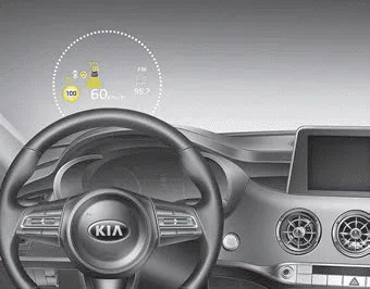
The head up display is a transparent display which projects a shadow of some information of the instrument cluster and navigation on the windshield glass.
- The head up display image on the windshield glass may not be visible when:
- Sitting posture prevents visibility.
- Wearing polarized sunglasses.
- There is an object on the cover of the head up display.
- Driving on a wet road.
- Lighting is turned on inside the vehicle.
- Any light comes from the outside.
- Wearing inadequate glasses for your eyesight. - If the head up display image is not shown well, adjust the height, rotation or illumination of the head up display in the LCD window. ❈ For more details, refer to “LCD window” in this chapter.
- When the head up display needs inspection or repair, consult an authorized Kia dealer.
- Do not place any accessories on the dashboard or attach any objects on the windshield glass.
✽ NOTICE
Installing window tint or any other type of metallic coating on the windshield can prevent the driver from seeing the Head Up Display images.
WARNING - Head up display
The Head up display is a supplemental system. Do not solely rely on the system, always drive safely, and pay attention to the driving conditions on the road.
✽ NOTICE
When replacing the front windshield glass of vehicles equipped with the head up display, replace it with a windshield glass designed for the head up display operation. Otherwise, duplicated images may be displayed on the windshield glass.
Head Up Display ON/OFF
The HUD display will be activated or deactivated in user setting mode while engine is ON.
Head Up Display Information
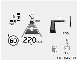
1. Turn By Turn navigation information
2. Road signs
3. Speedometer
4. Cruise setting speed
5. Smart Cruise Control (SCC) information
6. Blind-spot Collision Warning (BCW) system information
7.Warning lights (Low fuel)
8. AV mode information
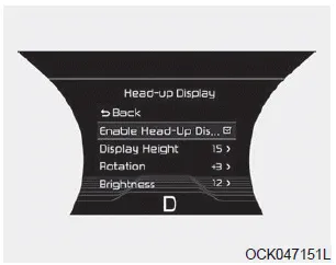
Head Up Display Setting
On the LCD display, you can change the head up display settings as follows.
1. Display height
2. Rotation
3. Brightness
4. Content select
5. Speedometer size
6. Speedometer color
❈ For more details, refer to “LCD window” in this chapter.


Other information:
Kia Stinger (CK) 2018-2023 Owner's Manual: Side Impact Sensor (SIS)
Description and operation Description • Side Impact Sensor (SIS) system consists of two Pressure Side Impact Sensor (P-SIS) installed at each center of the front door module (LH and RH), two SIS installed at each center pillar nearby (LH and RH) and two rear SIS installed in the rear pillar (LH and RH). • Pressure Side Impact Sensor is also called P-SIS because it detects pressure from collision at its mounting location.Kia Stinger (CK) 2018-2023 Owner's Manual: Automatic Transmission System
Components and components location Components 1. Torque converter 2. Electric Oil Pump (EOP) 3. Parking switch (Inhibitor switch) 4. Main connector 5. ATF Warmer Repair procedures Removal 1. Disconnect the negative (-) battery terminal. 2. Remove the stay (A) by loosening the bolts.Categories
- Manuals Home
- Kia Stinger Owners Manual
- Kia Stinger Service Manual
- New on site
- Most important about car
