Kia Stinger CK: Fuel Delivery System / Fuel Line
Repair procedures
| Removal |
Low Pressure Fuel Line [Engine Room <-> Extension Fuel Line]
| 1. |
Release the residual pressure in fuel line. (Refer to the Fuel Delivery System - "Release Residual Pressure in Fuel Line") |
| 2. |
Switch "OFF" the ignition and disconnect the negative (-) battery terminal. |
| 3. |
Remove the cowl top cover assembly. (Refer to Body (Interior and Exterior) - "Cowl Top Cover") |
| 4. |
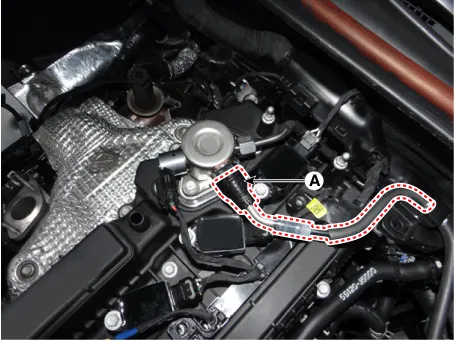
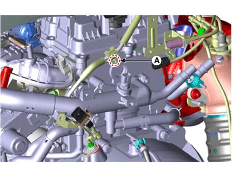
Disconnect the fuel feed tube quick-connector (A) which is connected from the high pressure fuel pump.
|
| 5. |
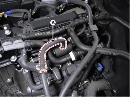
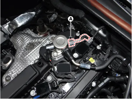
Disconnect the vapor hose (A) which is connected from the PCSV.
|
| 6. |
Remove the engine control module (ECM). (Refer to Engine Control System - "Engine Control Module (ECM)") |
| 7. |
Lift the vehicle. |
| 8. |
Remove the front-left wheel & tire and wheel house cover. |
| 9. |
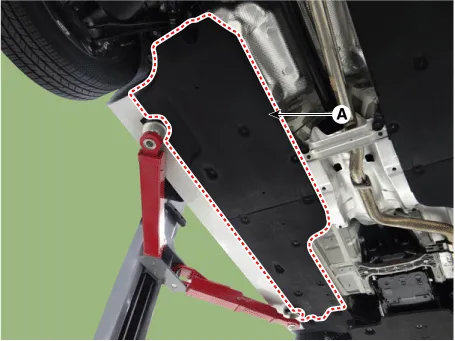
Remove the side under cover (A).
|
| 10. |
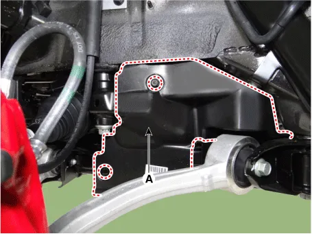
Remove the side cover (A).
|
| 11. |
Remove the brake line bracket (A) after removing mounting bolt.
|
| 12. |
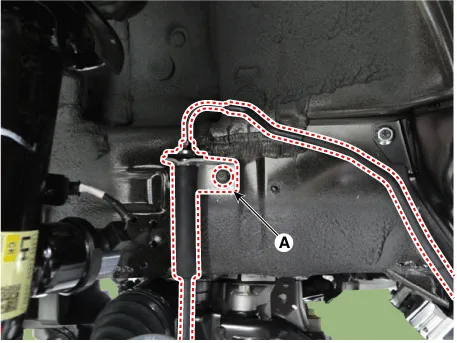
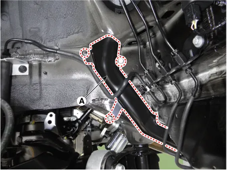
Remove the fuel line protector (A) after removing mounting nuts.
|
| 13. |
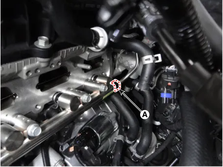
Disconnect the front vapor and fuel tube line quick-connector (A).
|
| 14. |
Down the vehicle. |
| 15. |
Remove the front vapor and fuel tube line. |
Low Pressure Fuel Line [Extension Fuel Line <-> Fuel Tank]
| 1. |
Release the residual pressure in fuel line. (Refer to the Fuel Delivery System - "Release Residual Pressure in Fuel Line") |
| 2. |
Switch "OFF" the ignition and disconnect the negative (-) battery terminal. |
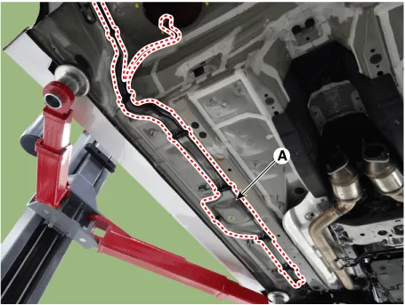
| 3. |
Remove the side under cover (A).
|
| 4. |
Disconnect the front vapor and fuel tube line quick-connector (A).
|
| 5. |
Remove the fuel tank. (Refer to Fuel Delivery System - "Fuel Tank") |
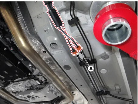
| 6. |
Remove the vapor tube and fule feed tube line fixing clips (A) by using a common driver.
|
High Pressure Fuel Pipe [Extension Fuel Line <-> Fuel Tank]
| 1. |
Release the residual pressure in fuel line. (Refer to the Fuel Delivery System - "Release Residual Pressure in Fuel Line") |
| 2. |
Switch "OFF" the ignition and disconnect the negative (-) battery terminal. |
| 3. |
Remove the cowl top cover assembly. (Refer to Body (Interior and Exterior) - Cowl Top Cover") |
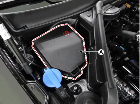
| 4. |
Remove the engine box cover (A).
|
| 5. |
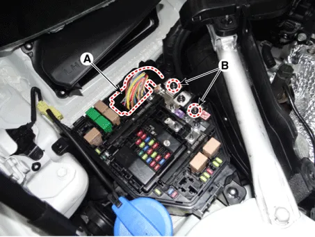
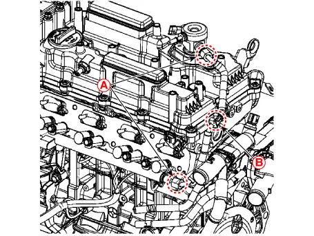
Disconnect the front control connector (A). |
| 6. |
Remove the groune terminal nuts (B).
|
| 7. |
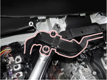
Remove the wiring protector (A).
|
| 8. |
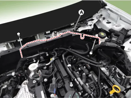
Remove the engine room panel (A).
|
| 9. |
Remove the high pressure fuel pipe.
|
| Installation |
| 1. |
Install the fuel line in the reverse order of removal. |
| 2. |
Install the high-pressure fuel pipe as follows.
|


Other information:
Kia Stinger (CK) 2018-2023 Service Manual: Emergency liftgate safety release
Your vehicle is equipped with the emergency liftgate safety release lever located on the bottom of the liftgate. When someone is inadvertently locked in the luggage compartment, the liftgate can be opened by doing as follows: 1. Remove the cover. 2. Push the release lever to the right. 3. Push up the liftgate. WARNING For emergencies, be fully aware of the location of the emergency liftgate safety release lever in the vehicle and how to open the liftgate if you are accidentally locked in the luggage compartment.Kia Stinger (CK) 2018-2023 Service Manual: Relay Box (Passenger Compartment)
Components and components location Component Location Integrated central control unit (ICU) Circuit (ICU Junction Block) Rear Sub Junction Block Description and operation Description Communication Network Diagram Abbreviation Explanation ACU Airbag Control Unit AFL Adaptive Front-Lighting System AMPCategories
- Manuals Home
- Kia Stinger Owners Manual
- Kia Stinger Service Manual
- New on site
- Most important about car
