Kia Stinger CK: Intake And Exhaust System / Intercooler
Components and components location
| Components |
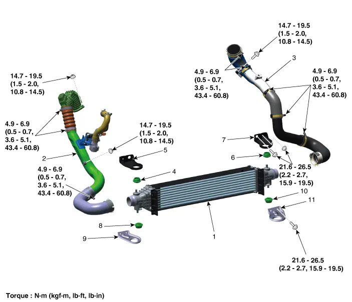
| 1. Intercooler 2. Intercooler inlet hose & pipe 3. Intercooler outlet hose & pipe 4. Intercooler upper mounting insulator (RH) 5. Intercooler upper mounting bracket (RH) 6. Intercooler upper mounting insulator (LH) |
7. Intercooler upper mounting
bracket (LH) 8. Intercooler lower mounting insulator (RH) 9. Intercooler lower mounting bracket (RH) 10. Intercooler lower mounting insulator (LH) 11. Intercooler lower mounting bracket (LH) |
Repair procedures
| Removal and Installation |
Intercooler Inlet Hose & Pipe
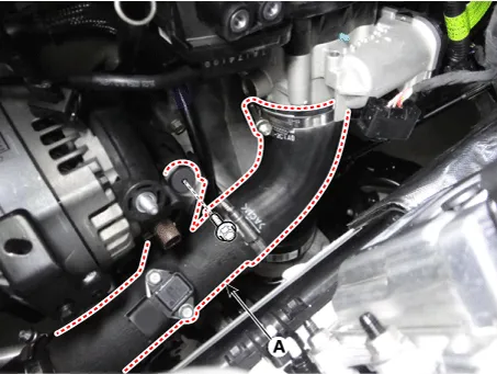
| 1. |
Remove the air intake hose. (Refer to Intake and Exhaust System - "Air Cleaner") |
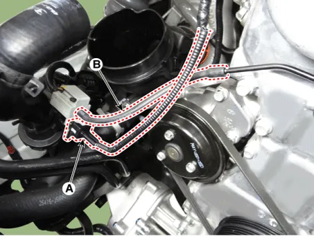
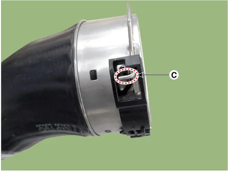
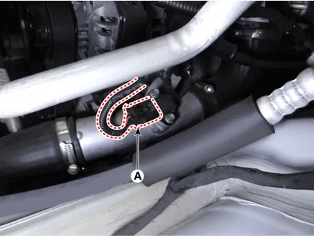
| 2. |
Disconnect the recirculation valve connector (A) and the vacuum hose (B).
|
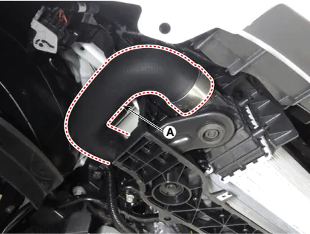
| 3. |
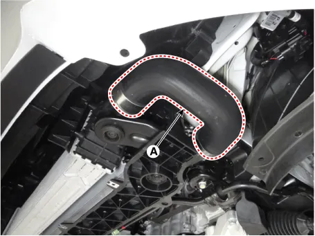
Remove the intercooler inlet hose & pipe assembly (A).
|

| 4. |
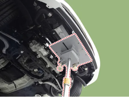
Remove the engine room front under cover. (Refer to Engine and Transmission Assembly - "Engine Room Under Cover") |
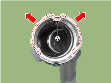
| 5. |
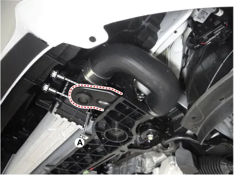
Remove the intercooler inlet hose (A).
|

| 6. |
Install in the reverse order of removal. |
Intercooler outlet Hose & Pipe
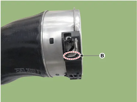
| 1. |
Disconnect the booster pressure sensor connector (A).
|
| 2. |
Remove the intercooler outlet hose & pipe assembly (A).
|
| 3. |
Remove the engine room front under cover. (Refer to Engine and Transmission Assembly - "Engine Room Under Cover") |
| 4. |
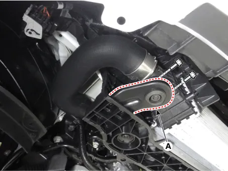
Remove the intercooler outlet hose (A).
|
| 5. |
Install in the reverse order of removal. |
Intercooler
| 1. |
Remove the engine room front under cover. (Refer to Engine and Transmission Assembly - "Engine Room Under Cover") |
| 2. |
Disconnect the intercooler inlet hose (A).
|
| 3. |
Disconnect the intercooler outlet hose (A).
|
| 4. |
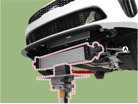
Install the jack under the intercooler to support the intercooler.
|
| 5. |
Remove the intercooler lower mounting bracket (A).
[LH]
[RH]
|
| 6. |
Remove the intercooler (A).
|
| 7. |
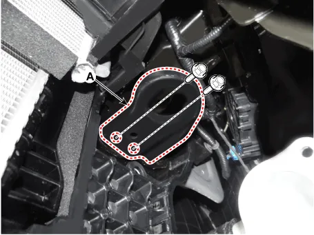
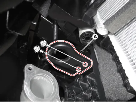
Remove the intercooler upper mounting bracket (A).
[LH]
[RH]
|
| 8. |
Install in the reverse order of removal. |


Other information:
Kia Stinger (CK) 2018-2023 Service Manual: Manifold Absolute Pressure Sensor (MAPS)
Specifications Specification Item Specification Output Voltage (V) 5 Pressure (KPa) 32.5 - 284 Operating Voltage (V) 4.5 - 5.5 Pressure [kPa (kgf/cm², psi)] Output Voltage (Vref = 5V) 32.Kia Stinger (CK) 2018-2023 Service Manual: Line Pressure Control Solenoid Valve (LINE_VFS)
Specifications Specifications Item Specification Control type N/L (Normal Low) Control pressure kpa (kgf/cm², psi) 0 - 519.75 (0 - 5.3, 0 - 75.38) Current (mA) 0 - 850 Coil resistance (Ω) 5.Categories
- Manuals Home
- Kia Stinger Owners Manual
- Kia Stinger Service Manual
- New on site
- Most important about car
