Kia Stinger CK: Engine And Transmission Assembly / Engine And Transmission Assembly
Repair procedures
| Removal and Installation |
|

Mark all wiring and hoses to avoid misconnection. |

| 1. |
Disconnect the negative battery terminal. |
| 2. |
Remove the engine cover. (Refer to Engine and Transmission Assembly - "Engine Cover") |
| 3. |
Remove the engine room under cover. (Refer to Engine and Transmission Assembly - "Engine Room Under Cover") |
| 4. |
Drain the coolant. (Refer to Cooling System - "Coolant") |
| 5. |
Recover the refrigerant and then disconnect the discharge line (A) and suction line (B) (Refer to Heating, Ventilation and Air conditioning - "Compressor")
|
| 6. |
Remove the air cleaner assembly. (Refer to Intake and Exhaust System - "Air Cleaner") |
| 7. |
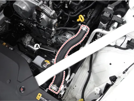
Disconnect the radiator upper hose (A).
|
| 8. |
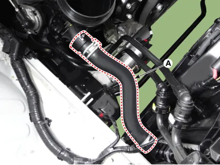
Disconnect the radiator lower hose (A).
|
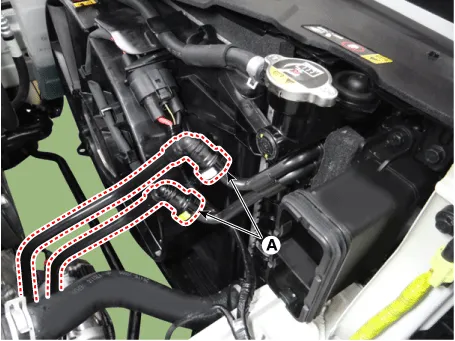
| 9. |
Disconnect the ATF cooler hoses (A).
|
| 10. |
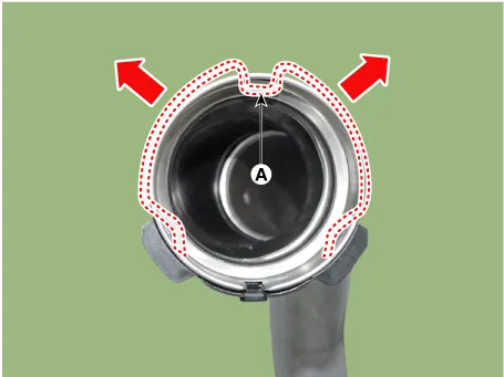
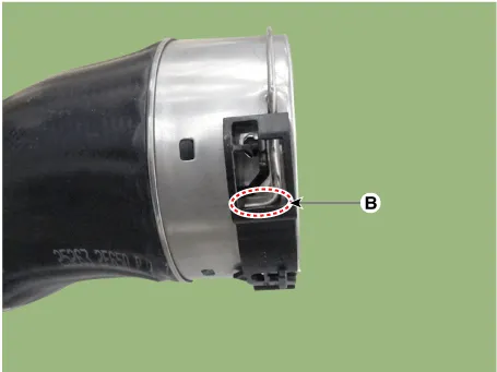
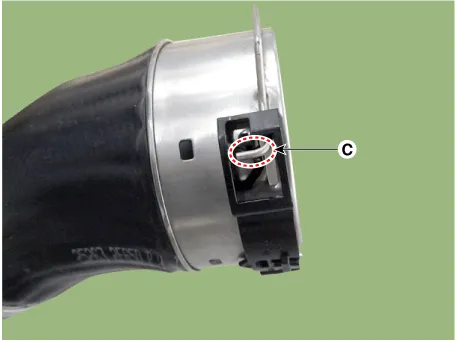
Remove the intercooler hose & pipe.
|
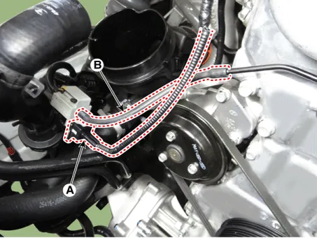

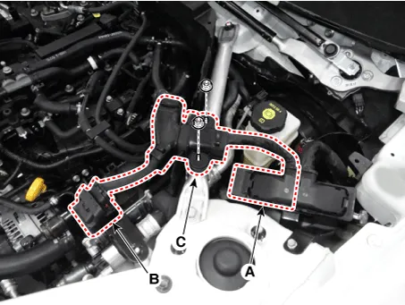
| 11. |
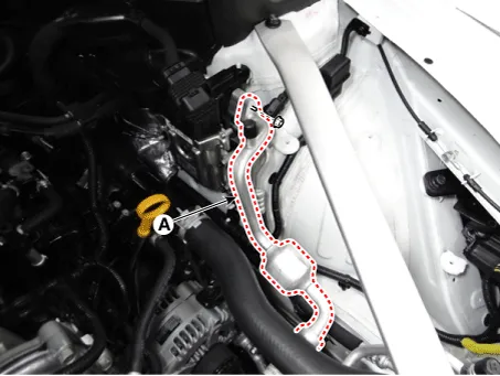
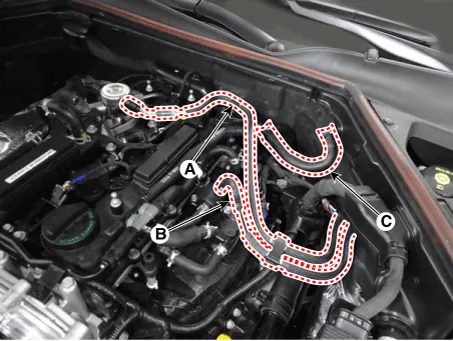
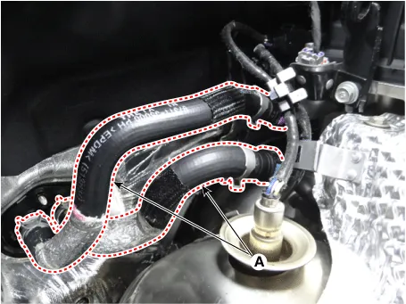
Disconnect the fuel hose (A) and purge control solenoid valve (PCSV) hose (B). |
| 12. |
Disconnect the brake booster vacuum hose (C).
|
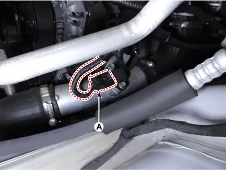
| 13. |
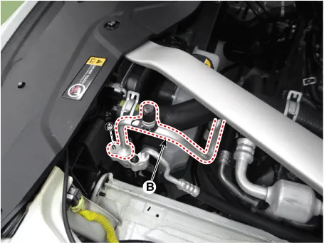
Disconnect the heater hose (A).
|
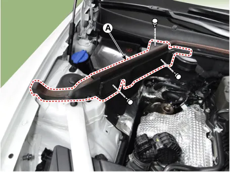
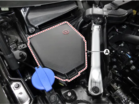
| 14. |
Remove the RH hood sealing cover (A).
|
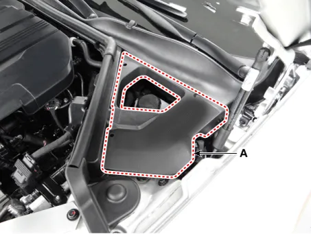
| 15. |
Remove the engine room cover (A).
|
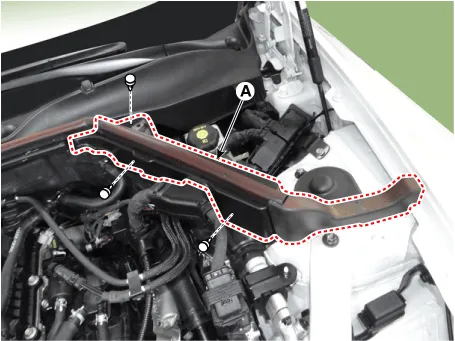
| 16. |
Remove the LH hood sealing cover (A).
|
| 17. |
Remove the cowl top cover. (Refer to Body (Interior and Exterior) -"Cowl Top Cover") |
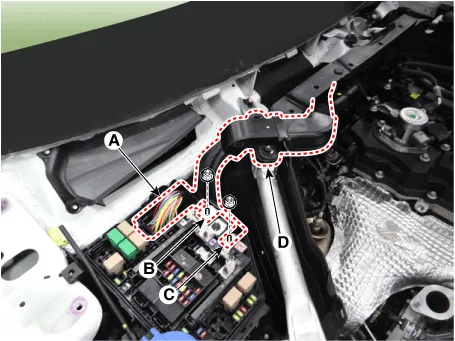
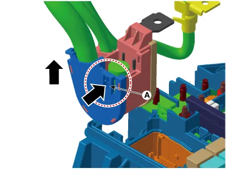
| 18. |
Disconnect the wiring connector and harness from the engine room.
|
| 19. |
Disconnect the R-MDPS connector (A).
|

| 20. |
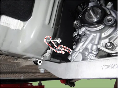
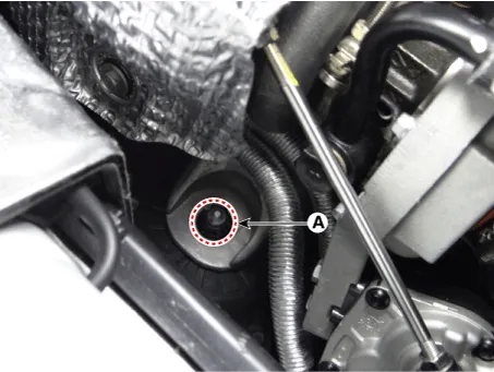
Disconnect the engine ground cable (A).
|
| 21. |
Disconnect the parking cable from the automatic transmission. (Refer to Automatic Transmission System - "Automatic transmission") |
| 22. |
Remove the front muffler. (Refer to Intake and Exhaust System - "Muffler") |
| 23. |
Remove the propeller shaft from the automatic transmission. (Refer to Driveshaft and Axle - "Propeller shaft") |
| 24. |
Remove the front wheel. |
| 25. |
Disconnect the universal joint assembly from the shaft joint. (Refer to Steering System - "Steering Column and Shaft") |
| 26. |
Remove the tie rod end ball joint from the knuckle. (Refer to Steering System - "Steering Gear Box") |
| 27. |
Remove the stabilizer link from the front shock absorber assembly. (Refer to Suspension System - Front Stabilizer Bar") |
| 28. |
Remove front driveshaft from the front axle. (If equipped with AWD system) (Refer to Driveshaft and Axle - "Front Driveshaft") |
| 29. |
Remove the lateral arm and compression arm from the sub frame. (Refer to Suspension System - "Front Lower Arm") |
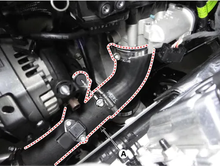
| 30. |
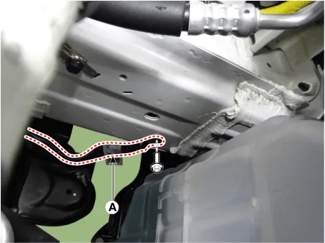
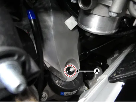
Disconnect the automatic transmission ground cable (A).
|
| 31. |
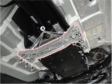
Support the engine and transmission assembly with a floor jack and then remove the sub frame mounting bolts (A).
[LH]
[RH]
|
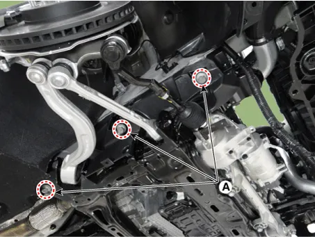

| 32. |
Remove the transmission mounting bracket mounting bolts (A).
|

| 33. |
Remove the engine and transaxle assembly by lifting vehicle.
|
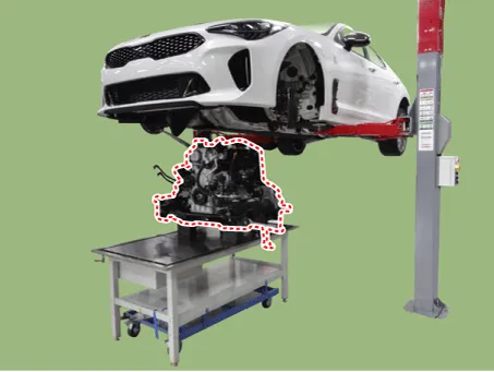
| 34. |
Remove the engine assembly from the sub frame.
|

| Installation |
Install the other parts in reverse order of removal.
Perform the following :
| • |
Adjust a shift cable. |
| • |
Refill engine with engine oil. |
| • |
Refill a transmission with fluid. |
| • |
Refill a radiator and a reservoir tank with engine coolant. |
| • |
Inspect for fuel leakage. |
| – |
After assemble the fuel line, turn on the ignition switch (do not operate the starter) so that the fuel pump runs for approximately two seconds and fuel line pressurizes. |
| – |
Repeat this operation two or three times, then check for fuel leakage at any point in the fuel line. |
| • |
Bleed air from the cooling system. |
| – |
Start engine and let it run until it warms up. (until the radiator fan operates 3 or 4 times.) |
| – |
Turn Off the engine. Check the level in the radiator, add coolant if needed. This will allow trapped air to be removed from the cooling system. |


Other information:
Kia Stinger (CK) 2018-2023 Service Manual: Starting the engine with a smart key
1.Carry the smart key or place it inside the vehicle. 2.Make sure the parking brake is firmly applied 3.Place the shift lever in P (Park). Depress the brake pedal fully. You can also start the engine when the shift lever is in the N (Neutral) position. 4.Press the engine start/stop button while depressing the brake pedal. 5.Do not wait for the engine to warm up while the vehicle remains stationary.Kia Stinger (CK) 2018-2023 Service Manual: Front Strut Assembly
Components and components location Components 1. Shock absorber 2. Spring lower pad 3. Coil spring 4. Dust cover 5. Bumper stopper 6. Spring upper cover 7. Strut bearing 8. Insulator assembly 9. Lock nut Repair procedures Removal [2WD] 1. Remove wheel nuts, front wheel and tire (A) from hub.Categories
- Manuals Home
- Kia Stinger Owners Manual
- Kia Stinger Service Manual
- New on site
- Most important about car
