Kia Stinger CK: ISG (Idle Stop and Go) system / ISG system malfunction
Contents:
The system may not operate when:
The system may not operate when an ISG related sensor or system error occurs.
The following will happen:
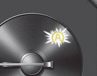
- The yellow AUTO STOP (
 ) indicator
on the instrument cluster will stay on after blinking for 5 seconds.
) indicator
on the instrument cluster will stay on after blinking for 5 seconds. - The light on the ISG OFF button will illuminate.
✽ NOTICE
If the ISG OFF button light is not turned off by pressing the ISG OFF button again or if the ISG system continuously does not work correctly, have your vehicle inspected by an authorized Kia dealer.
When the engine is in Idle Stop mode, it's possible to restart the engine without the driver taking any action. Before leaving the car or doing anything in the engine compartment, stop the engine by turning the ignition switch to the LOCK/OFF position or removing the ignition key.
✽ NOTICE
If the AGM battery is reconnected or replaced, ISG function will not operate immediately. If you want to use the ISG function, the battery sensor needs to be calibrated for approximately 4 hours with the ignition off. After calibration, turn the engine on and off 2 or 3 times.


Other information:
Kia Stinger (CK) 2018-2023 Owner's Manual: Adaptive Front-Lighting System (AFS)
Specifications Specifications Content Value AFS Nominal Voltage DC 13.5V Max Voltage 16.5V Rated Voltage DC 9.5 - 16V Operating Temperature -22 to 167°F (-30 to 75°) Operating Current MAX.Service data Service data Air Conditioner Item Specification Compressor Type 7HV x 17 Oil type & Capacity FD46XG OIL 100 ± 10g (3.52 ± 0.35 oz.) Pulley type 6PK - TYPE Displacement 175cc/rev Expansion valve Type Block type Refrigerant Type R-134a R-1234yf Capacity 600 ± 25g (20.Categories
- Manuals Home
- Kia Stinger Owners Manual
- Kia Stinger Service Manual
- New on site
- Most important about car
Contents
