
Kia Stinger CK: Steering System / Steering wheel
Contents:
Components and components location
| Components |

| 1. Steering wheel body 2. Remote control switch 3. Paddle shift 4. Lower cover |
5. Wiring 6. Damper 7. Upper cover 8. Upper cover |
Repair procedures
| Removal |
| 1. |
Disconnect the battery negative cable from the battery and then wait for at least 30 seconds. |
| 2. |
Turn the steering wheel so that the front wheels are facing straight ahead. |
| 3. |
Remove the driver airbag. (Refer to Restraint - "Driver Airbag (DAB) Module and Clock Spring") |
| 4. |
Disconnect the steering wheel connector.
|

| 5. |
Loosen the steering wheel bolt and then remove the steering wheel.
|
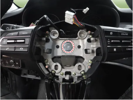

| 6. |
Install in the reverse order of removal. |
| Disassembly |
| 1. |
Loosen the screw and then remove the upper cover.
|


| 2. |
Loosen the damper screw and then remove the damper.
|

| 3. |
Loosen the paddle shift screw.
|


| 4. |
Using the driver, disconnect the paddle shift connector.
|

| 5. |
Loosen the remote control switch screw and then separate the remote control switch.
|

| 6. |
Disconnect the remote control switch connector and then remove the remote control switch & lower cover.
|

| 7. |
Disconnect the connector and then remove the steering wheel body.
|

| 8. |
Install in the reverse order of removal. |
Heated Steering wheel
Description and operation
| Description |
When manually selected, the heated steering wheel system improves the thermal comfort of the driver by heating the steering wheel.
| 1. |
Integrated Body Control Unit (IBU)
|

Schematic diagrams
| Circuit Diagram |

Terminal Function
|
Housing |
Pin |
Function |
Wire color |
|
Pad |
A |
GND |
Black |
|
B |
HEATER |
Yellow |
|
|
C |
NTC+ |
Gray |
|
|
D |
NTC¯ |
Black |
Repair procedures
| Inspection |
| NTC characteristic |
| 1. |
Measure the resistance of NTC and Heated pad. NTC resistance - 8.875 - 11.27 kΩ (25°C ±1°C) Heated pad resistance - 1.95 ± 0.2 Ω (22°C ±1°C) |
| 2. |
Measure the temperature.
|


Other information:
Kia Stinger (CK) 2018-2023 Service Manual: Parking Brake & Brake Fluid Warning Light
This warning light illuminates: Once you set the Engine Start/Stop Button to the ON position. - It illuminates for approximately 3 seconds When the parking brake is applied, the warning light will remain on. When the brake fluid level in the reservoir is low. - If the warning light illuminates with the parking brake released, it indicates the brake fluid level in reservoir is low.Components and components location Components 1. Air cleaner assembly 2. Air intake hose 3. Air cleaner adapter 4. Air duct Repair procedures Removal and Installation 1. Remove the engine cover. (Refer to Engine and Transmission Assembly - "Engine Cover") 2.Categories
- Manuals Home
- Kia Stinger Owners Manual
- Kia Stinger Service Manual
- New on site
- Most important about car
Contents
