Kia Stinger CK: Engine Control System / Heated Oxygen Sensor (HO2S)
Specifications
| Specification |
HO2S [Bank 1/Sensor 1]
|
Item |
Specification |
|
Heater Resistance (Ω) |
2.5 - 4.0 [20°C(68°F)] |
HO2S [Bank 1/Sensor 2]
|
Item |
Specification |
|
Heater Resistance (Ω) |
3.3 - 4.1 [20°C(69.8°F)] |
Description and operation
| Description |
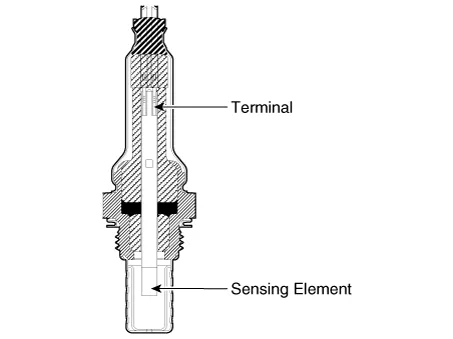
Heated Oxygen Sensor (HO2S), consisting of zirconium and alumina, is installed on both upstream and downstream of the Catalytic Converter to detect the air/fuel ratio and send it to the ECM.
The sensor must be heated in order to operate properly. To keep it heated, the sensor has a heater which is controlled by the ECM via a duty cycle signal. When the exhaust gas temperature is lower than the specified value, the heater warms up the sensor tip.
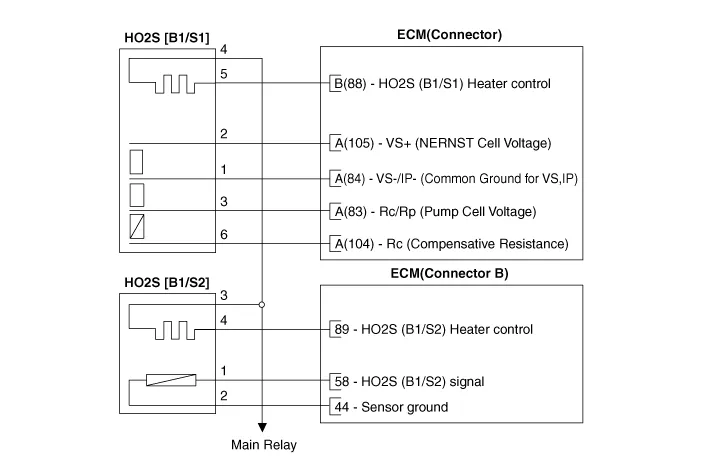
Schematic diagrams
| Circuit Diagram |
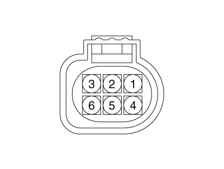
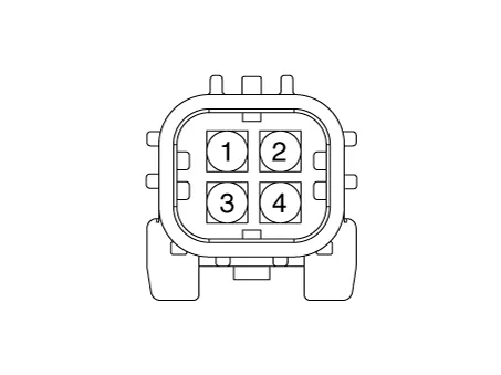
Harness Connector
[Bank 1 / Sensor 1]
[Bank 1 / Sensor 2]
Repair procedures
| Inspection |
| 1. |
Switch "OFF" the ignition. |
| 2. |
Disconnect the HO2S connector. |
| 3. |
Measure resistance between the HO2S terminals 4 and 5 [B1/S1].
|
| 4. |
Measure resistance between the HO2S terminals 3 and 4 [B1/S2].
|
| 5. |
Check that the resistance is within the specification. |
| Removal |
Note that the SST (Part No. : 09392-1Y100 or 09392-2H100) is useful when removing the heated oxygen sensor. |

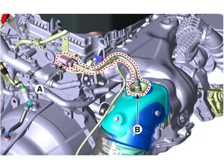
[Bank 1 / Sensor 1]
| 1. |
Switch "OFF" the ignition and disconnect the negative (-) battery terminal. |
| 2. |
Disconnect the connector (A), and then remove the sensor (B).
|
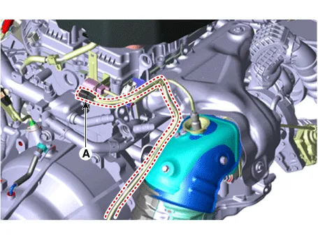
[Bank 1 / Sensor 2]
| 1. |
Switch "OFF" the ignition and disconnect the negative (-) battery terminal. |
| 2. |
Disconnect the connector (A).
|
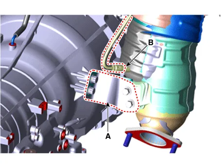
| 3. |
Lift the vehicle. |
| 4. |
Remove the catalytic converter bracket (A). |
| 5. |
Remove the sensor (B).
|
| Installation |
|
| 1. |
Install in the reverse order of removal.
|


Other information:
Kia Stinger (CK) 2018-2023 Service Manual: Luggage Side Trim
Components and components location Component Location 1. Rear transverse trim Repair procedures Replacement Put on gloves to protect your hands. • Use a plastic panel removal tool to remove interior trim pieces without marring the surface.Kia Stinger (CK) 2018-2023 Service Manual: Climate Control Air Filter
Repair procedures Filter inspection The climate control air filter should be replaced according to the maintenance schedule. If the vehicle is operated in severely polluted city or on dusty rough roads for a long period, it should be inspected more frequently and replaced earlier than schedule. When replacing the climate control air filter, replace in the following procedure and be careful not to damage other components.Categories
- Manuals Home
- Kia Stinger Owners Manual
- Kia Stinger Service Manual
- New on site
- Most important about car
