Kia Stinger CK: Hydraulic System / Oil Pump Unit (OPU)
Kia Stinger (CK) 2018-2023 Service Manual / Automatic Transmission System / Hydraulic System / Oil Pump Unit (OPU)
Components and components location
| Components Location |
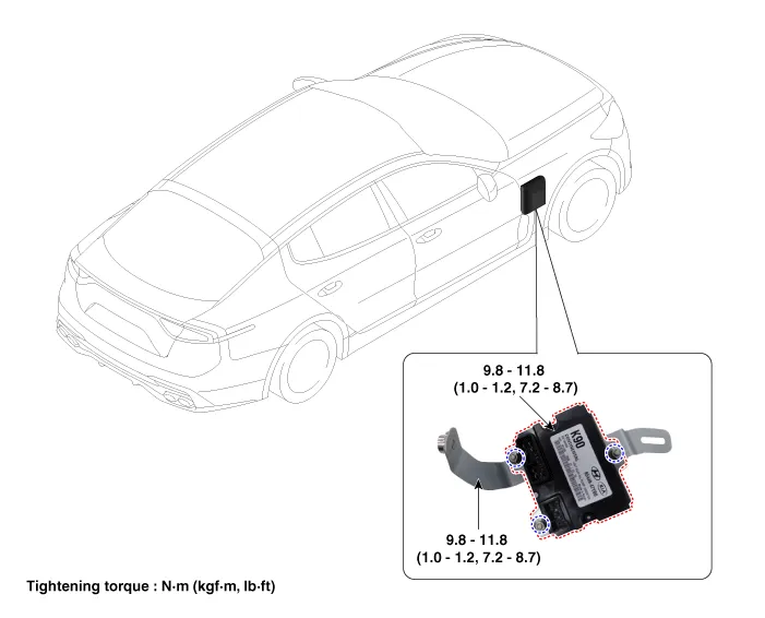
| 1. Oil Pump Unit (OPU) |
2. OPU bracket |
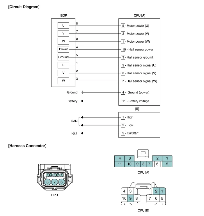
Schematic diagrams
| Circuit Diagram |
Repair procedures
| Removal |
| 1. |
Remove the integrated body control unit (IBU). (Refer to - Body Electrical System - "Integrated Body Control Unit") |
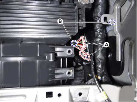
| 2. |
Disconnect the OPU connector (A) and then remove the OPU by loosening the OPU bracket nut (B).
|
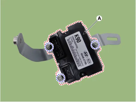
| 3. |
Remove the OPU (A) from the bracket.
|
| Installation |
| 1. |
Install in the reverse order of removal. |


Other information:
Kia Stinger (CK) 2018-2023 Service Manual: Winter driving
Severe weather conditions in the winter result in greater wear and other problems. To minimize the problems of winter driving, you should follow these suggestions: WARNING - Driving with summer tires Summer tires are equipped to provide the best driving performance on dry roads, varying according to specification. Do not use summer tires at temperatures below 7°C (45°F) or when driving on snow or ice.Kia Stinger (CK) 2018-2023 Service Manual: Barometric Pressure Sensor (BPS)
Specifications Specification Item Specification Output Voltage (V) 5 Pressure (KPa) 32.5 - 284 Operating Voltage (V) 4.5 - 5.5 Pressure [kPa (kgf/cm², psi)] Output Voltage (Vref = 5V) 32.Categories
- Manuals Home
- Kia Stinger Owners Manual
- Kia Stinger Service Manual
- New on site
- Most important about car

Copyright © 2026 www.kstinger.com 0.0087