
Kia Stinger CK: Hydraulic System / 8LR Brake Control Solenoid Valve (8LR/B_VFS)
Specifications
| Specifications |
|
Item |
Specification |
|
Control type |
N/L (Normal Low) |
|
Control pressure kpa (kgf/cm², psi) |
0 - 1,569.06 (0 - 16, 0 - 227.57) |
|
Current (mA) |
0 - 1,100 |
|
Coil resistance (Ω) |
5.3 ± 0.3 |
Components and components location
| Components Location |
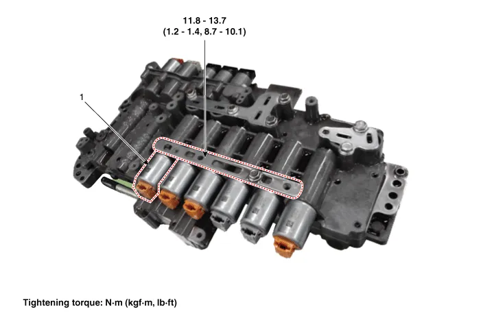
| 1. 8LR brake control solenoid
valve |
2. Solenoid valve support bracket
|
Description and operation
| Description |
| • |
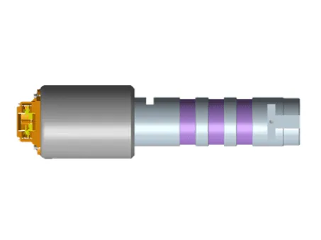
8LR brake control solenoid valve is a Variable Force Solenoid (VFS) type. |
| • |
When TCM supplies variable current to solenoid valve, hydraulic pressure of 8LR brake is controlled directly by solenoid valve. |
Solenoid Valve Operation Table
|
|
Solenoid Valve |
Brake |
|
8LR/B_VFS |
8LR/B |
|
|
P |
|
|
|
N |
● |
● |
|
1 |
● |
● |
|
2 |
|
|
|
3 |
|
|
|
4 |
|
|
|
5 |
|
|
|
6 |
|
|
|
7 |
|
|
|
8 |
● |
● |
|
REV |
● |
● |
Schematic diagrams
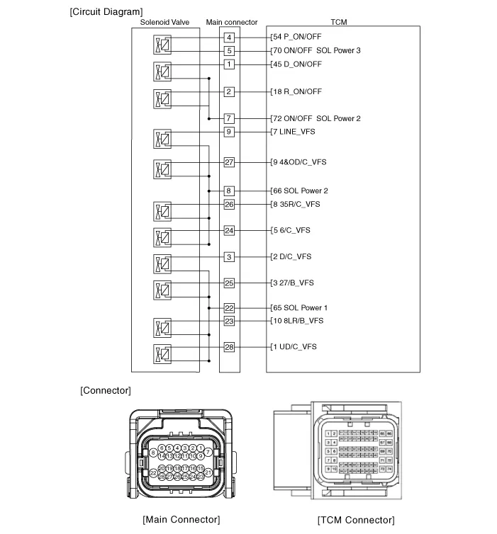
| Circuit Diagram |
Repair procedures
| Inspection |
| 1. |
Switch "OFF" ignition |
| 2. |
Disconnect the main connector (A).
|

| 3. |
Measure the resistance between power terminal (22) and signal terminal (23).
|
| Removal |
|

| 1. |
Remove the under cover. (Refer to Engine Mechanical System - "Engine Room Under Cover"). |
| 2. |
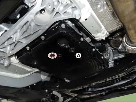
Remove the ATF drain plug (A), allow the fluid to drain out and then reinstall the drain plug.
|

| 3. |
Disconnect the main connector (A).
|
| 4. |
Remove the valve body cover.
|
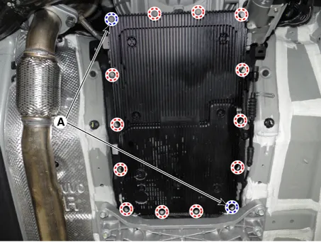
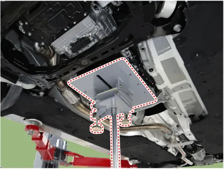
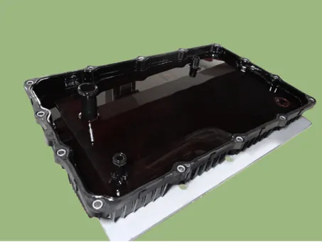
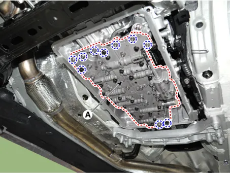
| 5. |
Remove the valve body assembly (A) after loosening the bolts.
|
| 6. |
Remove the E-module (A) after loosening the bolts.
|
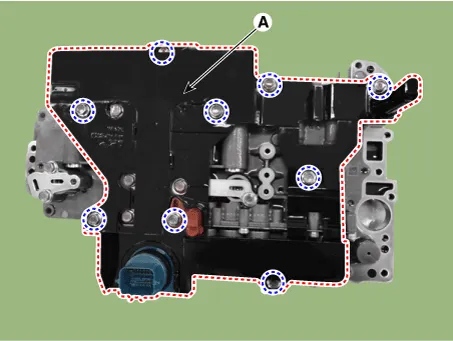
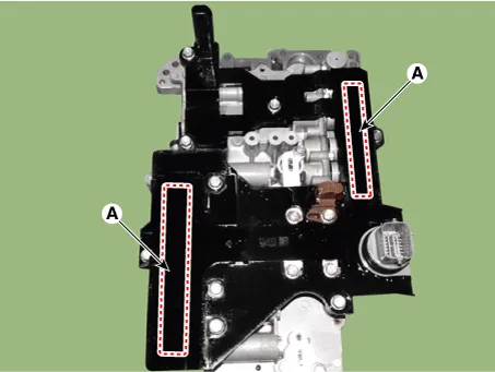
| 7. |
Remove the solenoid valve support bracket (A).
|
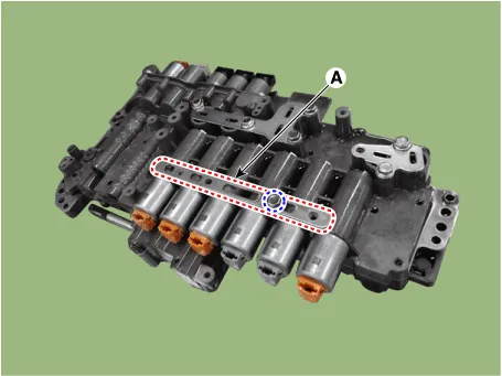
| 8. |
Remove the pin (A).
|

| 9. |
Remove the 8LR brake control solenoid valve (A).
|
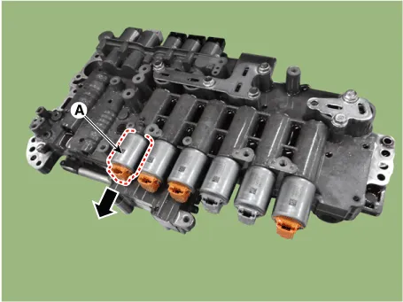
| Installation |
| 1. |
Install in the reverse order of removal.
|
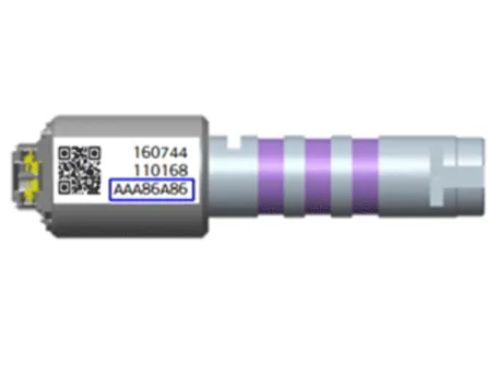
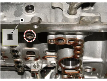
| 2. |
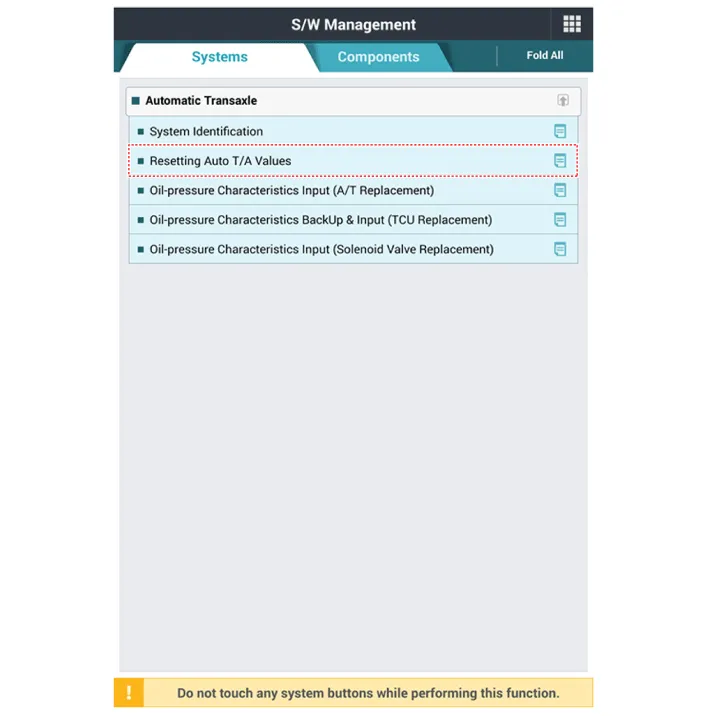
Perform the procedures below after installing.
|


Other information:
Repair procedures Tire Wear • Using tires and wheels other than the recommended sizes can cause unusual handling characteristics and poor vehicle control, resulting in a serious accident. 1. Measure the tread depth of the tires.Components and components location Component Location 1. Fender assembly Repair procedures Replacement Be careful not to damage the fender and body. When removing the clips, use a clip remover.Categories
- Manuals Home
- Kia Stinger Owners Manual
- Kia Stinger Service Manual
- New on site
- Most important about car
