Kia Stinger CK: Hydraulic System / 35R Clutch Control Solenoid Valve (35R/C_VFS)
Specifications
| Specifications |
|
Item |
Specification |
|
Control type |
N/H (Normal High) |
|
Control pressure kpa (kgf/cm², psi) |
0 - 1,569.06 (0 - 16, 0 - 227.57) |
|
Current (mA) |
0 - 1,100 |
|
Coil resistance (Ω) |
5.3 ± 0.3 |
Components and components location
| Components Location |
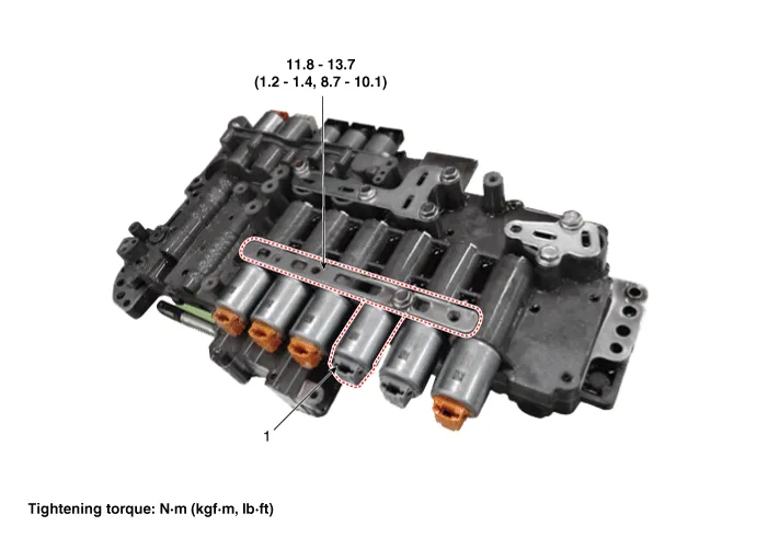
| 1. 35R clutch control solenoid
valve |
2. Solenoid valve support bracket
|
Description and operation
| Description |
| • |
35R clutch control solenoid valve is a Variable Force Solenoid (VFS) type. |
| • |
When TCM supplies variable current to solenoid valve, hydraulic pressure of 35R clutch is controlled directly by solenoid valve. |

Solenoid Valve Operation Table
|
|
Solenoid Valve |
Clutch |
|
35R/C_VFS |
35R/C |
|
|
P |
|
|
|
N |
● |
|
|
1 |
● |
|
|
2 |
● |
|
|
3 |
|
● |
|
4 |
● |
|
|
5 |
|
● |
|
6 |
● |
|
|
7 |
● |
|
|
8 |
● |
|
|
REV |
|
● |
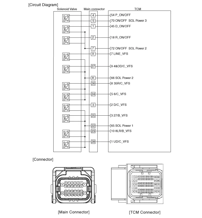
Schematic diagrams
| Circuit Diagram |
Repair procedures
| Inspection |
| 1. |
Switch "OFF" ignition |
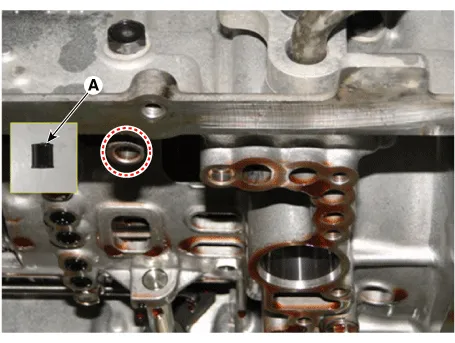
| 2. |
Disconnect the main connector (A).
|

| 3. |
Measure the resistance between power terminal (8) and signal terminal (26).
|
| Removal |
|

| 1. |
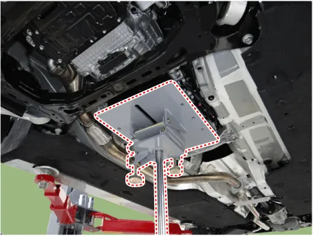
Remove the under cover. (Refer to Engine Mechanical System - "Engine Room Under Cover"). |
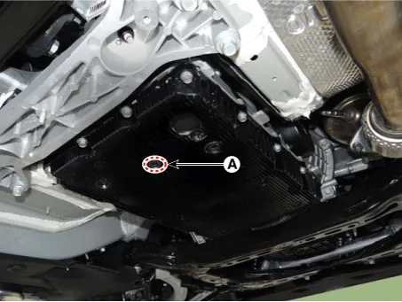
| 2. |
Remove the ATF drain plug (A), allow the fluid to drain out and then reinstall the drain plug.
|

| 3. |
Disconnect the main connector (A).
|
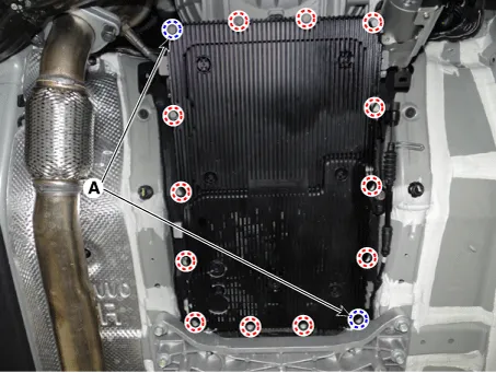
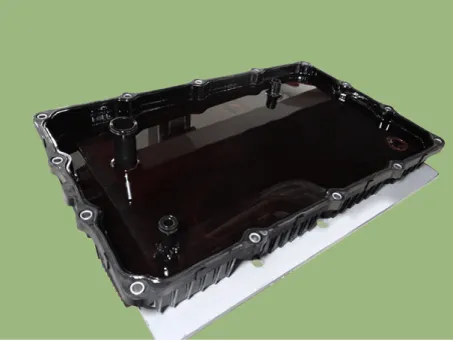
| 4. |
Remove the valve body cover.
|
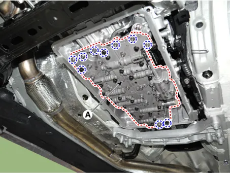
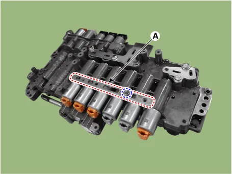
| 5. |
Remove the valve body assembly (A) after loosening the bolts.
|
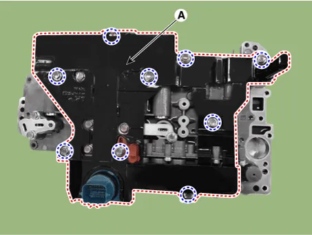
| 6. |
Remove the E-module (A) after loosening the bolts.
|
| 7. |
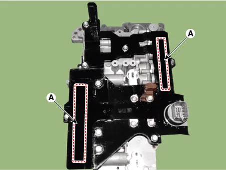
Remove the solenoid valve support bracket (A).
|
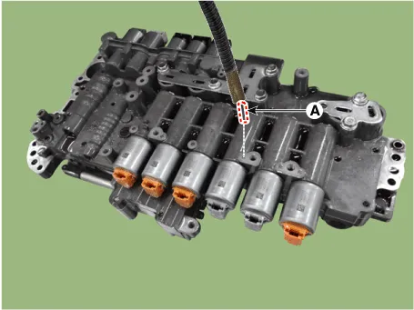
| 8. |
Remove the pin (A).
|
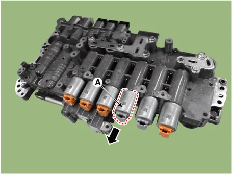
| 9. |
Remove the 35R clutch control solenoid vlave (A).
|
| Installation |
| 1. |
Install in the reverse order of removal.
|
| 2. |
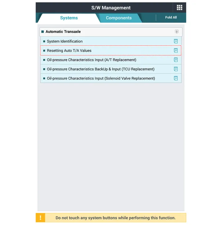
Perform the procedures below after installing.
|


Other information:
Kia Stinger (CK) 2018-2023 Service Manual: Field Effect Transistor (DATC)
Repair procedures Inspection 1. Turn the ignition switch ON. 2. Manually operate the control switch and measure the voltage of the blower motor. 3. Operate the control switch to raise the voltage up to high speed. Specification Fan Speed Manual Control Auto Control 1 4.Kia Stinger (CK) 2018-2023 Service Manual: Front Strut Assembly
Components and components location Components 1. Shock absorber 2. Spring lower pad 3. Coil spring 4. Dust cover 5. Bumper stopper 6. Spring upper cover 7. Strut bearing 8. Insulator assembly 9. Lock nut Repair procedures Removal [2WD] 1. Remove wheel nuts, front wheel and tire (A) from hub.Categories
- Manuals Home
- Kia Stinger Owners Manual
- Kia Stinger Service Manual
- New on site
- Most important about car
