Kia Stinger CK: Hydraulic System / 27 Brake Control Solenoid Valve (27/B_VFS)
Specifications
| Specifications |
|
Item |
Specification |
|
Control type |
N/L (Normal Low) |
|
Control pressure kpa (kgf/cm², psi) |
0 - 1,569.06 (0 - 16, 0 - 227.57) |
|
Current (mA) |
0 - 1,100 |
|
Coil resistance (Ω) |
5.3 ± 0.3 |
Components and components location
| Components Location |
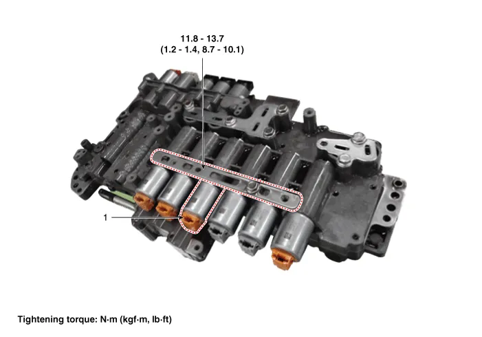
| 1. 27 brake control solenoid
valve |
2. Solenoid valve support bracket
|
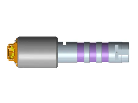
Description and operation
| Description |
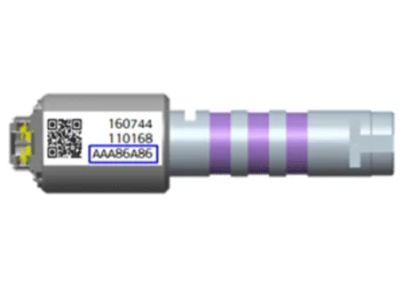
| • |
27 brake control solenoid valve is a Variable Force Solenoid (VFS) type. |
| • |
When TCM supplies variable current to solenoid valve, hydraulic pressure of 27 brake is controlled directly by solenoid valve. |
Solenoid Valve Operation Table
|
|
Solenoid Valve |
Brake |
|
27/B_VFS |
27/B |
|
|
P |
|
|
|
N |
|
|
|
1 |
|
|
|
2 |
● |
● |
|
3 |
|
|
|
4 |
|
|
|
5 |
|
|
|
6 |
|
|
|
7 |
● |
● |
|
8 |
|
|
|
REV |
|
|
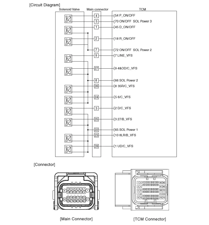
Schematic diagrams
| Circuit Diagram |
Repair procedures
| Inspection |
| 1. |
Switch "OFF" ignition |
| 2. |
Disconnect the main connector (A).
|

| 3. |
Measure the resistance between power terminal (22) and signal terminal (25).
|
| Removal |
|

| 1. |
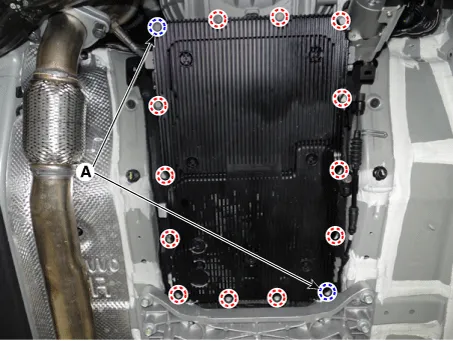
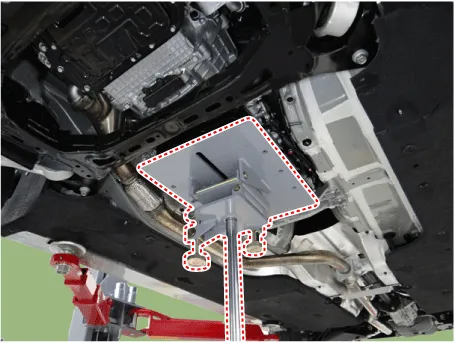
Remove the under cover. (Refer to Engine Mechanical System - "Engine Room Under Cover"). |
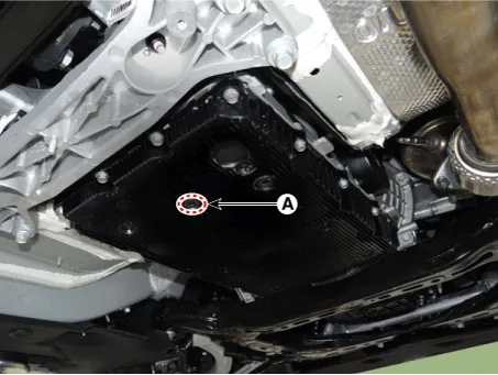
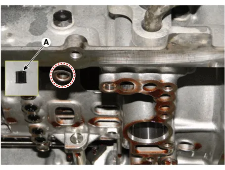
| 2. |
Remove the ATF drain plug (A), allow the fluid to drain out and then reinstall the drain plug.
|

| 3. |
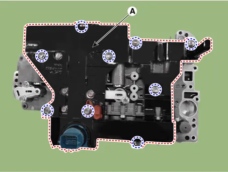
Disconnect the main connector (A).
|
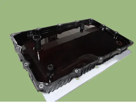
| 4. |
Remove the valve body cover.
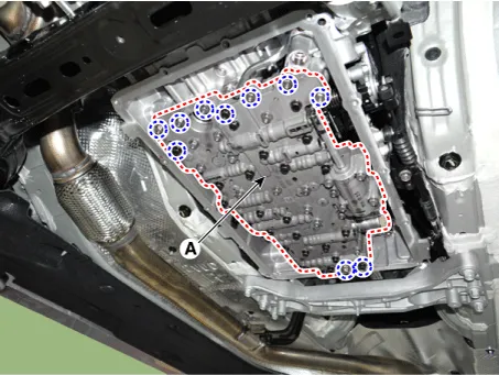
|
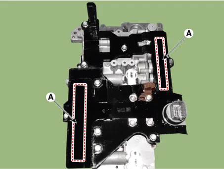
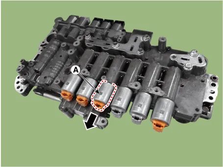
| 5. |
Remove the valve body assembly (A) after loosening the bolts.
|
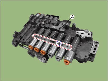
| 6. |
Remove the E-module (A) after loosening the bolts.
|
| 7. |
Remove the solenoid valve support bracket (A).
|
| 8. |
Remove the pin (A).
|
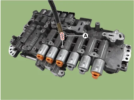
| 9. |
Remove the 27 brake control solenoid valve (A).
|
| Installation |
| 1. |
Install in the reverse order of removal.
|
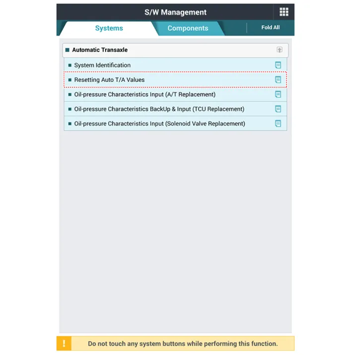
| 2. |
Perform the procedures below after installing.
|


Other information:
Kia Stinger (CK) 2018-2023 Service Manual: Owner maintenance
The following lists are vehicle checks and inspections that should be performed by the owner or an authorized Kia dealer at the frequencies indicated to help ensure safe, dependable operation of your vehicle. Any adverse conditions should be brought to the attention of your dealer as soon as possible. These Owner Maintenance Checks are generally not covered by warranties and you may be charged for labor, parts and lubricants used.Kia Stinger (CK) 2018-2023 Service Manual: Automatic Transmission System
Components and components location Components 1. Torque converter 2. Electric Oil Pump (EOP) 3. Parking switch (Inhibitor switch) 4. Main connector 5. ATF Warmer Repair procedures Removal 1. Disconnect the negative (-) battery terminal. 2. Remove the stay (A) by loosening the bolts.Categories
- Manuals Home
- Kia Stinger Owners Manual
- Kia Stinger Service Manual
- New on site
- Most important about car
