Kia Stinger CK: Lubrication System / Balance Shaft & Oil Pump
Repair procedures
| Removal |
BSM (Balance Shaft Module) Chain System
| 1. |
Remove the timing chain. (Refer to Timing System - "Timing Chain") |
| 2. |
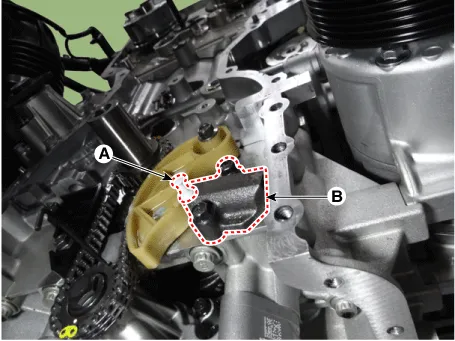
Install a stopper pin (A) after compressing the balance shaft chain tensioner. |
| 3. |
Remove the balance shaft chain tensioner (B).
|
| 4. |
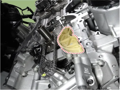
Remove the balance shaft chain tensioner arm (A).
|
| 5. |
Remove the balance shaft chain guide (A).
|
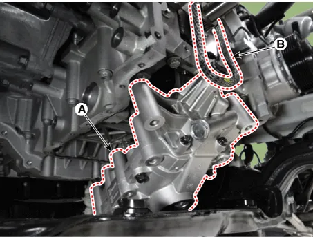
| 6. |
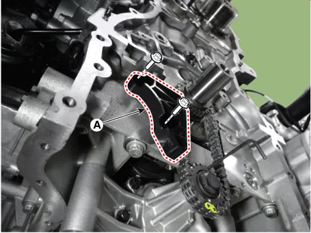
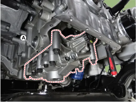
Remove the balance shaft module (BSM) after removing the BSM mounting bolts.
|

| 7. |
Remove the balance shaft module (BSM) (A) from the chain (B).
|
| 8. |
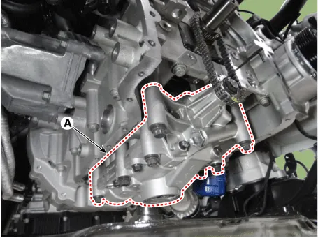
Remove the balance shaft chain (A).
|
BSM (Balance Shaft Module)
| 1. |
Remove the oil pan. (Refer to Lubrication System - "Oil Pan") |
| 2. |
Set No.1 cylinder to TDC/compression.
|
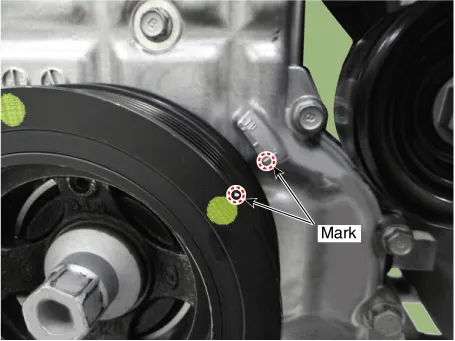
| 3. |
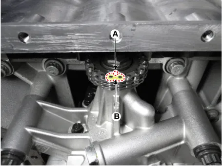
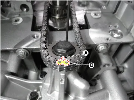
Put a mark on the timing chain (A) corresponding to the timing mark (B) of the sprocket.
|
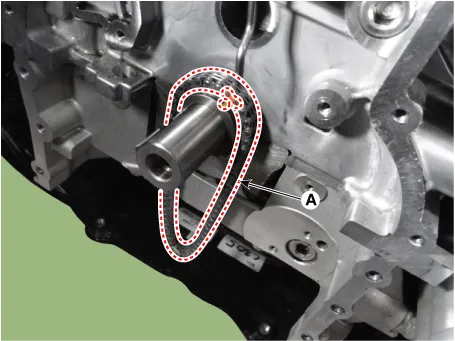
| 4. |
Insert a stopper pin (A) into the hole on the tensioner after compressing the balance shaft chain tensioner piston.
|
| 5. |
Remove the BSM mounting bolts.
|

| 6. |
Remove the BSM balance shaft module (BSM) (A) while taking off the chain from the sprocket.
|
| Installation |
BSM(Balance Shaft Module) Chain System
| 1. |
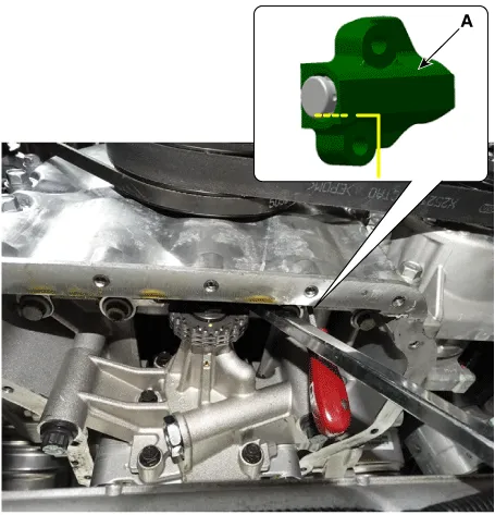
The key (A) of crankshaft should be aligned with the mating face of main bearing cap. As a result of this, the piston of No.1 cylinder is placed at the top dead center on compression stroke.
|
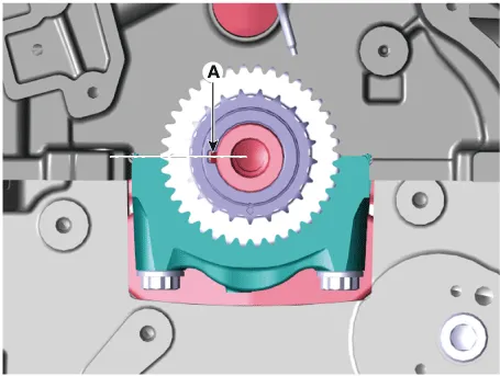
| 2. |
Match the timing marks of balance shaft chain sprocket (A) and balance shaft chain (B), then install the balance shaft chain (C).
|

| 3. |
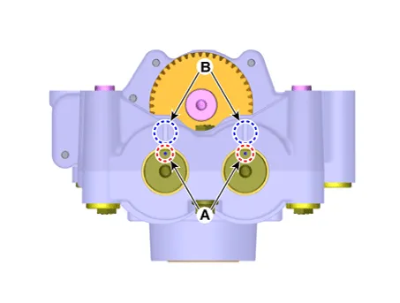
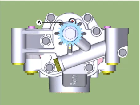
Insert a stopper pin (A) on the BSM to hold the sprocket at the reference position with the timing mark (B) aligned with the timing notch (C). [Front]
[Rear]
|

| 4. |
Install the balance shaft module (BSM).
|
| 5. |
Install the balance shaft chain guide (A).
|
| 6. |
Install the balance shaft chain tensioner arm (A).
|
| 7. |
Install the balance shaft chain tensioner (B) then remove the stopper pin (A).
|
| 8. |
Remove the stopper pin (A) of balance shaft module.
|
| 9. |
After rotating crankshaft 2 revolutions in regular direction (clockwise viewed from front), confirm that the timing mark and notch are aligned at the reference position. |
| 10. |
Install the other parts in the reverse order of removal. |
BSM (Balance Shaft Module)
| 1. |
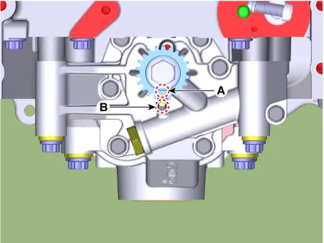
Insert a stopper pin (A) on the BSM to hold the sprocket at the reference position with the timing mark (B) aligned with the timing notch (C). [Front]
[Rear]
|
| 2. |
Install the balance shaft module (BSM).
|
| 3. |
Remove the stopper pin (A) from the BSM.
|
| 4. |
Remove the stopper pin (A) from the tensioner.
|
| 5. |
Confirm that the sprocket timing mark (A) is visually aligned with center of adjacent cast timing notch (B).
|
| 6. |
Install the other parts in the reverse order of removal. |


Other information:
Kia Stinger (CK) 2018-2023 Service Manual: Cluster Fascia Panel
Components and components location Component Location 1. Cluster fascia panel Repair procedures Replacement Put on gloves to protect your hands. • Use a plastic panel removal tool to remove interior trim pieces without marring the surface.Repair procedures Replacement Do not apply sealant to the body. 1. Using a screwdriver, remove the tailgate lifter (B) after removing the socket clips (A). 2. Push the socket of the lifter into the bracket for installation.Categories
- Manuals Home
- Kia Stinger Owners Manual
- Kia Stinger Service Manual
- New on site
- Most important about car
