
Kia Stinger CK: Charging System / Alternator
Specifications
| Specification |
▷ 13.5V, 150A
|
Item |
Specification |
|
Rated voltage |
13.5V , 150A |
|
Speed in use |
0 - 18,000 rpm |
|
Pin |
1 |
|
Voltage regulator |
IC Regulator built in type |
|
Default regulated voltage (V) [COM terminal] |
14.39 - 15.43 [-35°C(31°F)] |
|
14.15 - 14.95 [25°C(77°F)] |
|
|
13.23 - 14.49 [140°C(284°F)] |
|
|
Pully Type |
OAP |
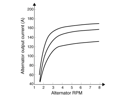
Description and operation
| Description |
The Alternator has eight built-in diodes, each rectifying AC current to DC current.
Therefore, DC current appears at alternator "B" terminal.
In addition, the charging voltage of this alternator is regulated by the battery voltage detection system.
The alternator is regulated by the battery voltage detection system.
The main components of the alternator are the rotor, stator, rectifier, capacitor brushes, bearings and V-ribbed belt pulley.
The brush holder contains a built-in electronic voltage regulator.

| 1. Brush 2. Drive belt pulley 3. Rotor 4. Stator |
Components and components location
| Components |
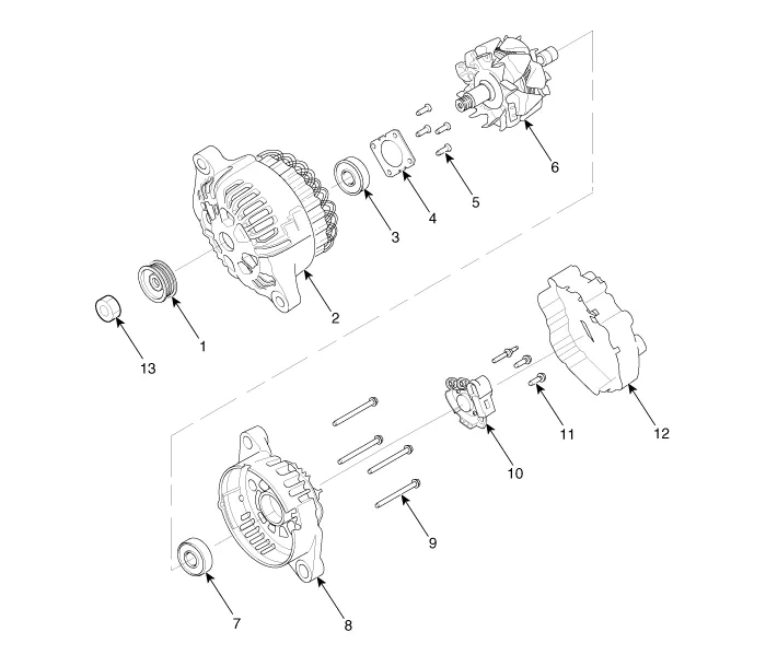
| 1. Pulley 2. Front bracket 3. Front bearing 4. Bearing cover 5. Bearing cover bolt 6. Rotor 7. Rear bearing |
8. Rear bracket8. Shield 9. Through bolt 10. Brush holder assembly 11. Brush holder bolt 12. Rear cover 13. Nut |
Schematic diagrams
| Circuit Diagram |
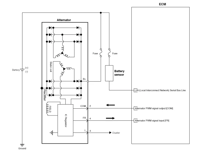
|

Repair procedures
| Removal |
| 1. |
Switch "OFF" the ignition and disconnect the negative (-) battery terminal. |
| 2. |
Remove the drive belt. (Refer to Engine Mechanical System - "Drive Belt") |
| 3. |
Disconnect the alternator connector (B), and remove the cable (A) from alternator "B" terminal.
|
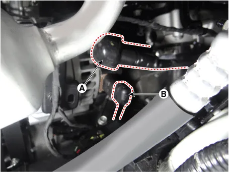
| 4. |
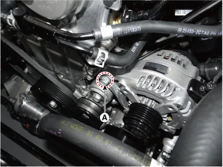
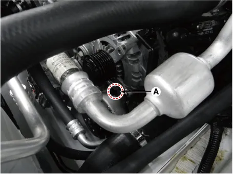
Remove the alternator lower bolt and upper bolt (A).
|
| 5. |
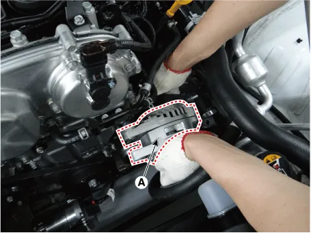
Remove the alternator (A).
|

| Installation |
| 1. |
Install in the reverse order of removal. |
| 2. |
Install the drive belt. (Refer to Engine Mechanical System - "Drive Belt") |


Other information:
Kia Stinger (CK) 2018-2023 Service Manual: Rear Back Armrest
Components and components location Component Location 1. Rear seat armrest Repair procedures Replacement Put on gloves to protect your hands. • Use a plastic panel removal tool to remove interior trim pieces without marring the surface.Kia Stinger (CK) 2018-2023 Service Manual: Emergency liftgate safety release
Your vehicle is equipped with the emergency liftgate safety release lever located on the bottom of the liftgate. When someone is inadvertently locked in the luggage compartment, the liftgate can be opened by doing as follows: 1. Remove the cover. 2. Push the release lever to the right. 3. Push up the liftgate. WARNING For emergencies, be fully aware of the location of the emergency liftgate safety release lever in the vehicle and how to open the liftgate if you are accidentally locked in the luggage compartment.Categories
- Manuals Home
- Kia Stinger Owners Manual
- Kia Stinger Service Manual
- New on site
- Most important about car
