Kia Stinger CK: Front Suspension System / Front Lower Arm
Repair procedures
| Removal |
[2WD Lateral arm]
| 1. |
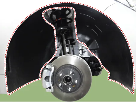
Remove wheel nuts, front wheel and tire (A) from hub.
|


| 2. |
Remove the front wheel guard.
|
| 3. |
Remove the front stabilizer bar. (Refer to Suspension System - "Front Stabilizer Bar") |
| 4. |
Remove the engine room side cover. D 2.2 R VGT (Refer to Engine Mechanical System - "Engine Room Under cover") G 2.0 T-GDI THETA II (Refer to Engine Mechanical System - "Engine Room Under cover") G 3.3 T-GDI LAMBDA II (Refer to Engine Mechanical System - "Engine Room Under cover") |
| 5. |
Remove the lateral arm.
|
| 6. |
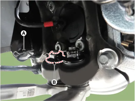
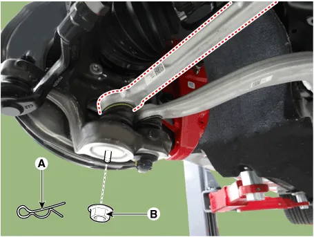
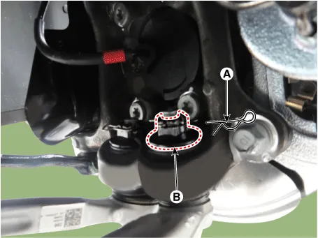
Loosen the lateral arm pin (A) and nut (B).
|
| 7. |
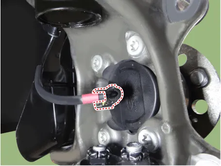
Disonnec the wheel speed sensor connector.
|
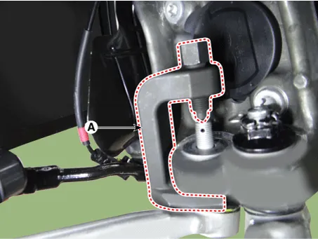
| 8. |
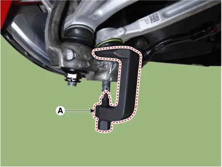
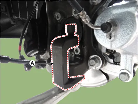
Remove the lateral arm by using the ball joint remover (A).
|
| 9. |
Install in the reverse order of removal.
|
| 10. |
Check the front alignment. (Refer to Suspension System - "Alignment") |
[AWD Lateral arm]
| 1. |
Remove wheel nuts, front wheel and tire (A) from hub.
|
| 2. |
Remove the engine room side cover. D 2.2 R VGT (Refer to Engine Mechanical System - "Engine Room Under cover") G 2.0 T-GDI THETA II (Refer to Engine Mechanical System - "Engine Room Under cover") G 3.3 T-GDI LAMBDA II (Refer to Engine Mechanical System - "Engine Room Under cover") |
| 3. |
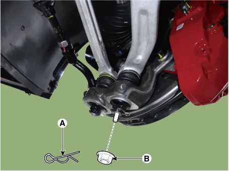
Loosen the lateral arm pin (A) and nut (B).
|
| 4. |
Remove the lateral arm by using the ball joint remover (A).
|
| 5. |
Remove the lateral arm.
|
| 6. |
Install in the reverse order of removal.
|
| 7. |
Check the front alignment. (Refer to Suspension System - "Alignment") |
[2WD Compression arm]
| 1. |
Remove wheel nuts, front wheel and tire (A) from hub.
|
| 2. |
Remove the front wheel guard.
|
| 3. |
Remove the front stabilizer bar. (Refer to Suspension System - "Front Stabilizer Bar") |
| 4. |
Remove the engine room side cover. D 2.2 R VGT (Refer to Engine Mechanical System - "Engine Room Under cover") G 2.0 T-GDI THETA II (Refer to Engine Mechanical System - "Engine Room Under cover") G 3.3 T-GDI LAMBDA II (Refer to Engine Mechanical System - "Engine Room Under cover") |
| 5. |
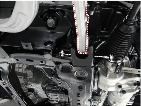
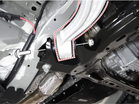
Loosen the compression arm bolt & nut from the subframe.
|
| 6. |
Loosen the compression arm pin (A) and nut (B).
|
| 7. |
Disonnec the wheel speed sensor connector.
|
| 8. |
Remove the compression arm by using the ball joint remover (A).
|
| 9. |
Install in the reverse order of removal.
|
| 10. |
Check the front alignment. (Refer to Suspension System - "Alignment") |
[AWD Compression arm]
| 1. |
Remove wheel nuts, front wheel and tire (A) from hub.
|
| 2. |
Remove the front wheel guard.
|
| 3. |
Remove the engine room side cover. D 2.2 R VGT (Refer to Engine Mechanical System - "Engine Room Under cover") G 2.0 T-GDI THETA II (Refer to Engine Mechanical System - "Engine Room Under cover") G 3.3 T-GDI LAMBDA II (Refer to Engine Mechanical System - "Engine Room Under cover") |
| 4. |
Loosen the compression arm pin (A) and nut (B).
|
| 5. |
Remove the compression arm by using the ball joint remover (A).
|

| 6. |
Loosen the compression arm bolt & nut from the subframe.
|
| 7. |
Install in the reverse order of removal.
|
| 8. |
Check the front alignment. (Refer to Suspension System - "Alignment") |
| Inspection |
| 1. |
Check the lower arm bushings for damage or signs of aging. If necessary, replace the lower arm assembly. |
| 2. |
Check the lateral arm for damage or deformation. |
| 3. |
Check the all bolts. |


Other information:
Kia Stinger (CK) 2018-2023 Service Manual: Children Always in the Rear
WARNING - Restraint Location Never install a child or infant seat on the front passenger's seat. A child riding in the front passenger seat can be forcefully struck by an inflating airbag and seriously injured. WARNING - Hot Child Restraint A child restraint system can become very hot if it is left in a closed vehicle on a sunny day. Be sure to check the seat cover, buckles and latches before placing a child in the restraint system.Battery saver function The purpose of this feature is to prevent the battery from being discharged if the lights are left in the ON position. The system automatically shuts off the parking lights 30 seconds after the ignition key is removed and the driver’s door is opened and closed. With this feature, the parking lights will turn off automatically if the driver parks on the side of the road at night and opens the driver’s side door.Categories
- Manuals Home
- Kia Stinger Owners Manual
- Kia Stinger Service Manual
- New on site
- Most important about car
