Kia Stinger CK: Automatic Transmission Control System / E-Shifter
Components and components location
| Components |

| 1. E-Shifter 2. Parking release actuator |
3. Parking release cable 4. Parking release lever |
Schematic diagrams
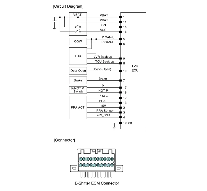
| Circuit Diagram |
Description and operation
| Description |
| • |
Operating Principle: Any change in the lever position is detected and transmitted via electric signals from the electronic shift lever ECU to the TCM. |
| • |
Function |
| – |
Gear shifting signal transmission |
| – |
Shift lever display |
| – |
Shift locking |
| – |
System failure diagnosis |
| • |
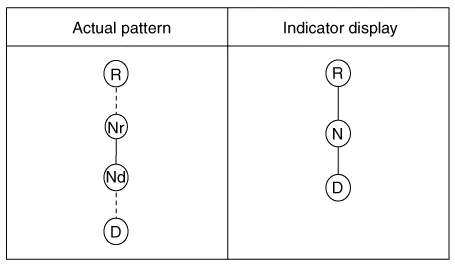
Electronic shift lever operation pattern
|
| • |
Operation order Flow diagram
|
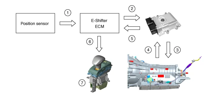
| 1) |
The lever position is detected and the data is sent to the electronic shift lever ECM. |
| 2) |
The lever position information is transmitted from the electronic shift lever ECM to the TCM (CAN + Hard wire). |
| 3) |
The TCM controls the AT so that the mode reflects the lever position. |
| 4) |
The TCM checks the information on the final shift mode of the AT. |
| 5) |
The TCM sends the information on the final shift mode to the electronic shift lever ECM. (CAN) |
| 6) |
The Electronic shift lever ECM sends the information on final shift mode to the indicator. |
| 7) |
Current information on the final shift mode appears on the indicator. |
Repair procedures
| Removal |
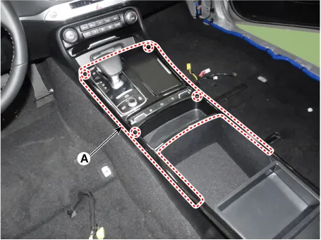
| 1. |
Remove the upper console cover (A) using the remover.
|
| 2. |
Disconnect the main connector (A).
|
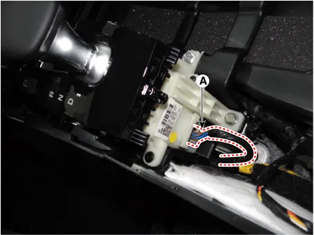
| 3. |
Loosen the E-shifter mounting screws (A).
|
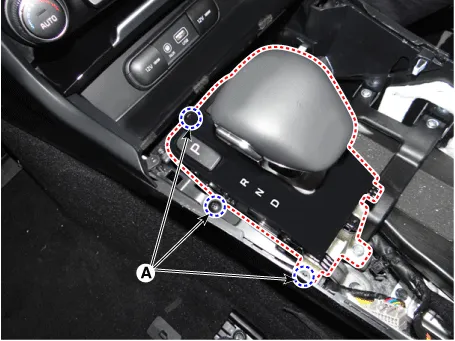
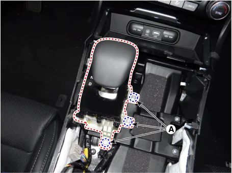
| 4. |
Loosen the E-shifter mounting bolts (A).
|
| Installation |
| 1. |
Install in the reverse order of removal. |


Other information:
Kia Stinger (CK) 2018-2023 Service Manual: Refrigerant Line
Repair procedures Replacement 1. Discharge refrigerant from the refrigeration system. 2. Replace faulty tube or hose. Cap the open fittings immediately to keep moisture or dirt out of the system.Kia Stinger (CK) 2018-2023 Service Manual: Adaptive Front-Lighting System (AFS) Unit
Components and components location Components Schematic diagrams Schematic Diagrams Description and operation Description AFS Unit (ECU) AFS located in Cockpit Module is provided information of vehicle (steering wheel signal, vehicle speed, inclination of vehicle). Based on provided information, it calculates algorithm and adjust Low beam of H/Lamp.Categories
- Manuals Home
- Kia Stinger Owners Manual
- Kia Stinger Service Manual
- New on site
- Most important about car
