Kia Stinger CK: Driveshaft and axle / Front Axle Assembly
Components and components location
| Components |
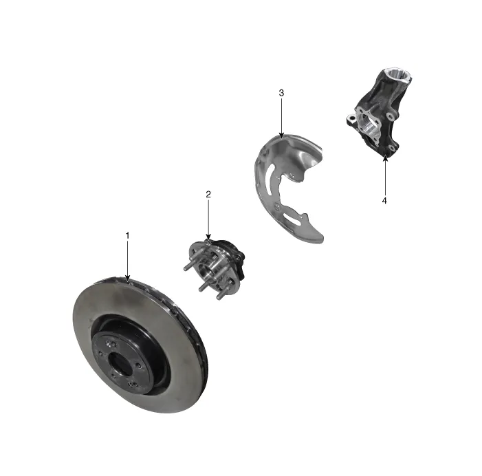
| 1. Front brake disc 2. Hub assembly |
3. Dust cover 4. Front knuckle |
Repair procedures
| Removal |
| [2WD] |
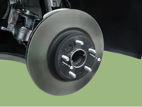
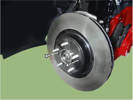
| 1. |
Remove wheel nuts, front wheel and tire (A) from front hub.
|


| 2. |
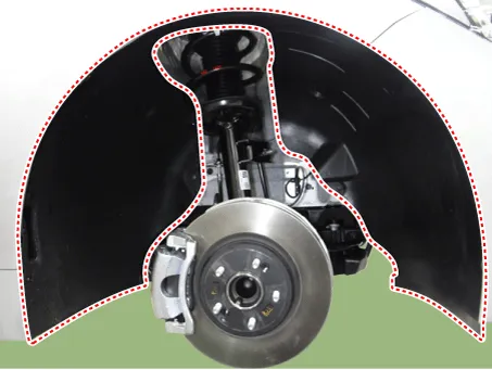
Remove the front wheel guard.
|
| 3. |
Remove the front stabilizer bar. (Refer to Suspension System - "Front Stabilizer Bar") |
| 4. |
Remove the engine room side cover. D 2.2 R VGT (Refer to Engine Mechanical System - "Engine Room Under cover") G 2.0 T-GDI THETA II (Refer to Engine Mechanical System - "Engine Room Under cover") G 3.3 T-GDI LAMBDA II (Refer to Engine Mechanical System - "Engine Room Under cover") |
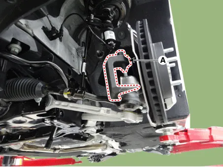
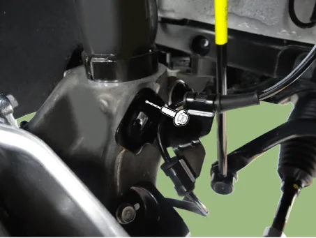
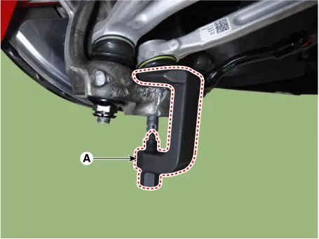
| 5. |
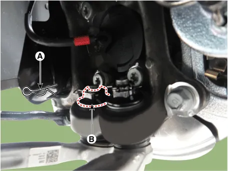
Loosen the lateral arm pin (A) and nut (B).
|
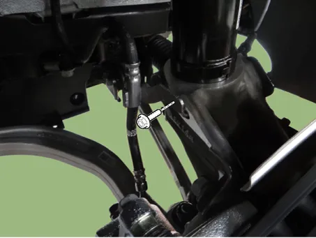
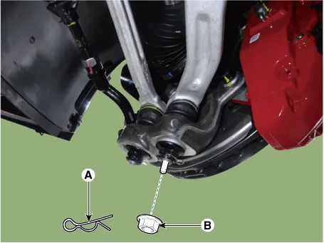
| 6. |
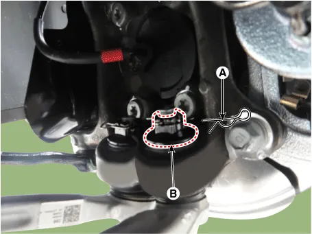
Loosen the compression arm pin (A) and nut (B).
|
| 7. |
Loosen the compression arm bolt & nut from the sub frame.
|
| 8. |
Disonnect the wheel speed sensor connector.
|
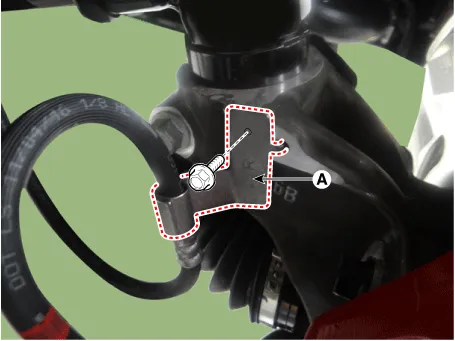
| 9. |
Remove the lateral arm by using the ball joint remover (A).
|
| 10. |
Remove the compression arm by using the ball joint remover (A).
|
| 11. |
Remove the brake caliper. (Refer to Brake System - "Front Disc Brake") |
| 12. |
Remove the tie rod end nut.
|
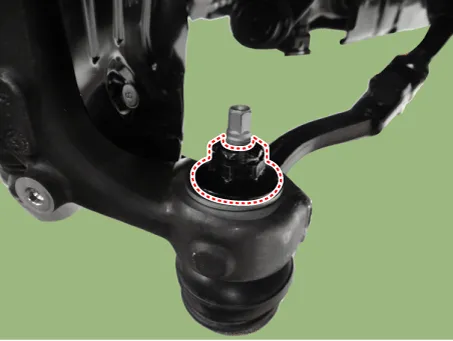
| 13. |
Remove the knuckle by using the ball joint remover (A).
|
| 14. |
Loosen the screw, and then remove the brake disc.
|
| 15. |
Loosen the dust cover bolt and then remove the dust cover.
|
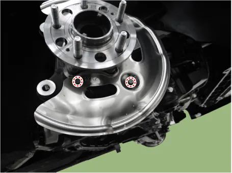
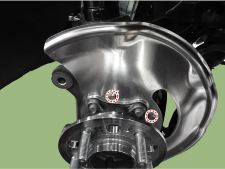
| 16. |
Loosen the hub assembly bolts and then remove the hub assembly.
|
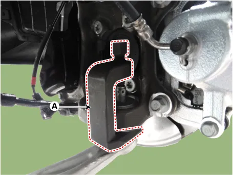
| 17. |
Loosen the wheel speed sensor bracket bolt and then remove the wheel speed sensor bracket.
|
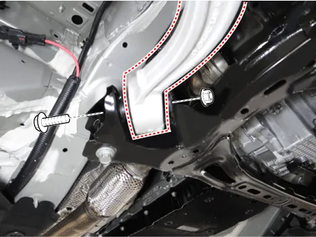
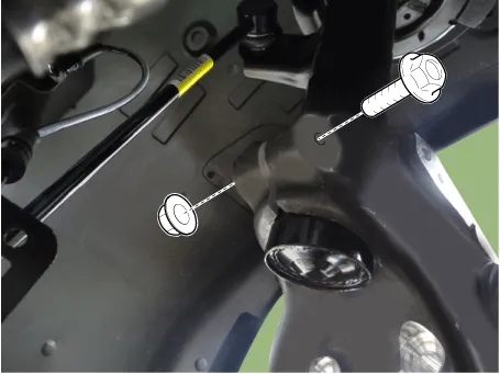
| 18. |
Loosen the brake caliper hose bracket bolt.
|
| 19. |
Loosen the brake cooling cover bolts.
|
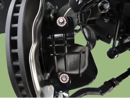
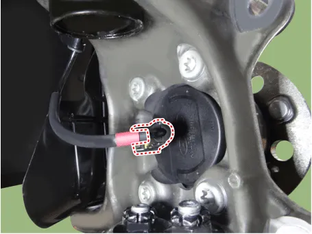
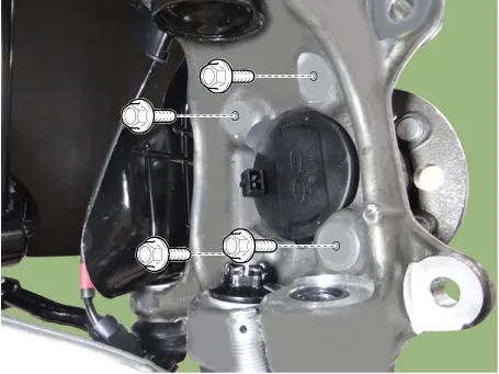
| 20. |
Loosen the knuckle upper bolt & nut.
|
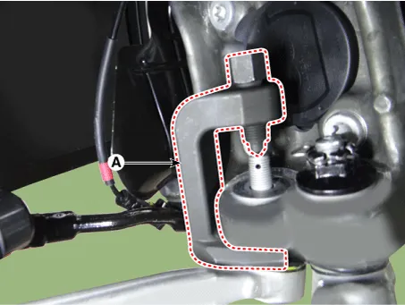
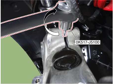
| 21. |
Remove the knuckle by using the SST (0K517-J5100).
|
| 22. |
Install in the reverse order of removal. |
| 23. |
Check the front alignment. (Refer to Suspension System - "Alignment") |
| [AWD] |
| 1. |
Remove wheel nuts, front wheel and tire (A) from front hub.
|
| 2. |
Remove the brake caliper. (Refer to Brake System - "Front Disc Brake") |
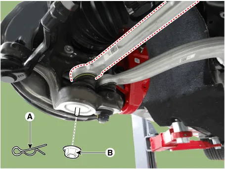
| 3. |
Loosen the lateral arm pin (A) and nut (B).
|
| 4. |
Remove the lateral arm by using the ball joint remover (A).
|
| 5. |
Loosen the compression arm pin (A) and nut (B).
|
| 6. |
Remove the compression arm by using the ball joint remover (A).
|

| 7. |
Remove the tie rod end nut.
|
| 8. |
Remove the knuckle by using the ball joint remover (A).
|
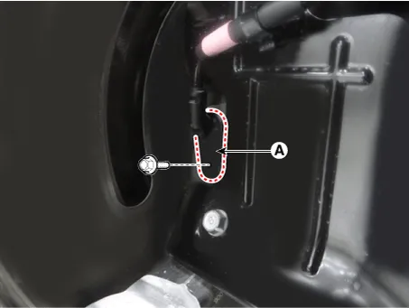
| 9. |
Remove the brake hose bracket (A).
|
| 10. |
Loosen the screw, and then remove the brake disc.
|
| 11. |
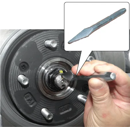
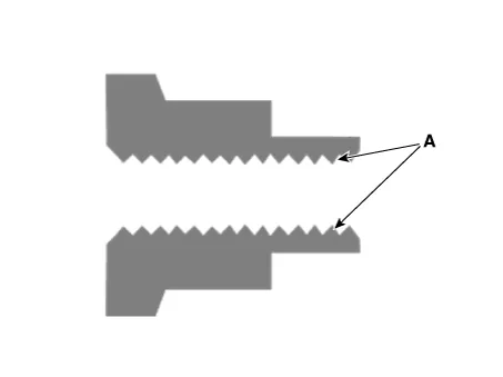
By hammering on a chisel, unlock the driveshaft lock hub nut caulking.
|
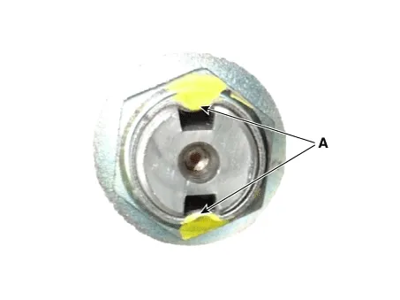
| 12. |
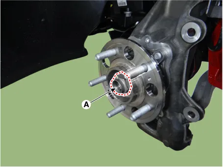
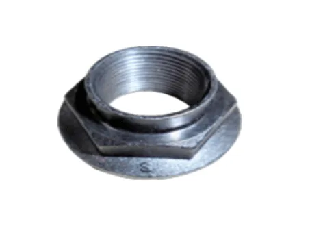
Loosen the caulking nut (A) and then separate the hub assembly from the drive shaft.
|
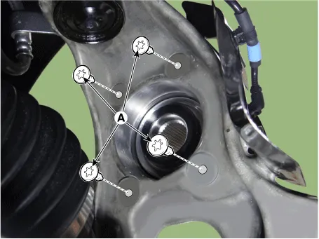
| 13. |
Loosen the hub assembly bolts (A) and then remove the hub assembly.
|
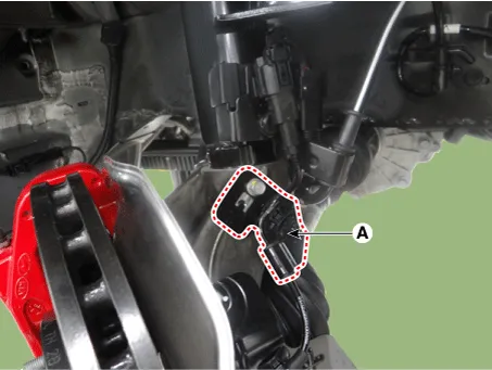
| 14. |
Loosen the wheel speed sensor bolt (A) and then disconnect the wheel speed sensor.
|
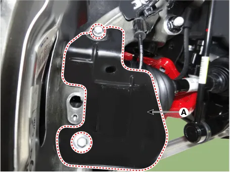
| 15. |
Remove the brake cooling cover (A).
|
| 16. |
Remove the wheel speed sensor bracket (A).
|
| 17. |
Loosen the knuckle upper bolt & nut.
|
| 18. |
Remove the knuckle by using the SST (0K517-J5100).
|
| 19. |
Install in the reverse order of removal. |
| 20. |
Check the front alignment. (Refer to Suspension System - "Alignment") |
| Inspection |
| 1. |
Check the hub for cracks and the splines for wear. |
| 2. |
Check the brake disc for scoring and damage. |
| 3. |
Check the knuckle for cracks. |
| 4. |
Check the bearing for cracks or damage. |


Other information:
Kia Stinger (CK) 2018-2023 Service Manual: Automatic Transmission Control System
Description and operation Description Automatic transmission control system relies on various measurements to determine the current control status and determine the necessary compensation values. These values are used to control the actuators and achieve the desired control output. Control System Composition Shift By Wire (SBW) System Composition ▶ Operating Principle – Instead of cable, the system uses electronic signals to shift between the P-R-N-D gears.Kia Stinger (CK) 2018-2023 Service Manual: Oil Pump Unit (OPU)
Components and components location Components Location 1. Oil Pump Unit (OPU) 2. OPU bracket Schematic diagrams Circuit Diagram Repair procedures Removal 1. Remove the integrated body control unit (IBU). (Refer to - Body Electrical System - "Integrated Body Control Unit") 2.Categories
- Manuals Home
- Kia Stinger Owners Manual
- Kia Stinger Service Manual
- New on site
- Most important about car
