Kia Stinger CK: Airbag Module / Driver Airbag (DAB) Module and Clock Spring
Description and operation
| Description |
Driver Airbag (DAB) is installed in the steering wheel and electrically connected to SRSCM via the clock spring.
It protects the driver by deploying the airbag when frontal crash occurs. The SRSCM determines deployment of the Driver Airbag (DAB).
Never attempt to measure the circuit resistance of the airbag module (squib) even if you are using the specified tester. If the circuit resistance is measured with a tester, accidental airbag deployment will result in serious personal injury. |

Components and components location
| Components |
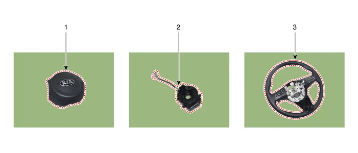
| 1. Driver Airbag (DAB) 2. Clock Spring |
3. Steering wheel |
Repair procedures
| Inspection |
Airbag module
If any improper parts are found during the following inspection, replace the airbag module with a new one.
Never attempt to measure the circuit resistance of the airbag module (squib) even if you are using the specified tester. If the circuit resistance is measured with a tester, accidental airbag deployment will result in serious personal injury. |
| 1. |
Check pad cover for dents, cracks or deformities. |
| 2. |
Check the airbag module for dents, cracks or deformities. |
| 3. |
Check hooks and connectors for damage, terminals for deformities, and harness for binding. |
| 4. |
Check airbag inflator case for dents, cracks or deformities |
Clock Spring
| 1. |
If, as a result of the following checks, even one abnormality is discovered, replace the clock spring with a new one. |
| 2. |
Check connectors and protective tube for damage, and terminals for deformities.
|

| Removal |
| 1. |
Set the front tires straight-ahead before assembling the steering wheel.
|
| 2. |
Disconnect the battery negative terminal, and wait for at least three minutes before beginning to work. |
| 3. |
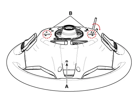
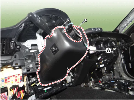
Remove the driver side airbag module. Insert a tool into the lower hole (A) and then rotate both sides of the tool (B) in the direction of the arrow to release it.
|
| 4. |
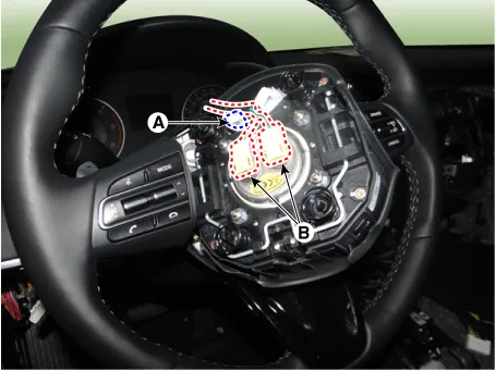
Disconnect the airbag connector (A) and horn connector (B).
|
| 5. |
Remove the steering wheel. (Refer to Steering System - "Steering Wheel") |
| 6. |
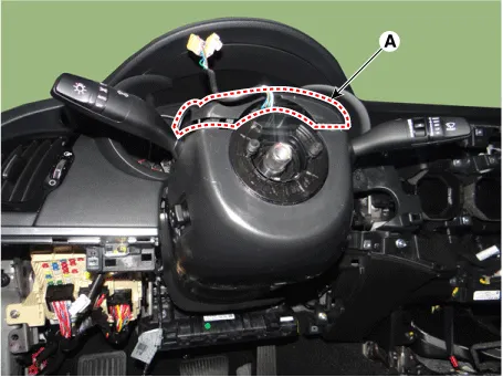
Remove the upper steering wheel column shroud (A).
|
| 7. |
Loosen the screws and remove the lower shroud (A).
|
| 8. |
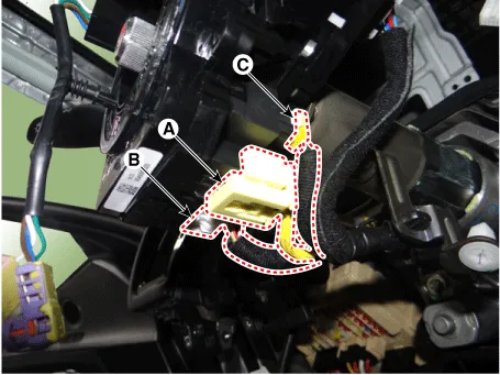
Separate the clock spring wiring harness connector (A) and the horn wiring harness connector (B) from the clock spring.
|
| Installation |
| 1. |
Set the front tires straight-ahead before assembling the steering wheel.
|
| 2. |
Connect the clock spring harness connector and horn harness connector to the clock spring. |
| 3. |
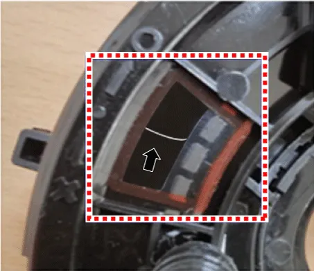
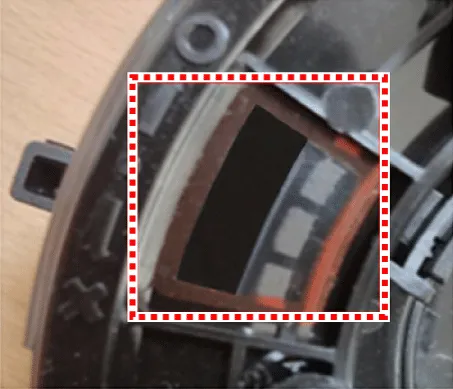
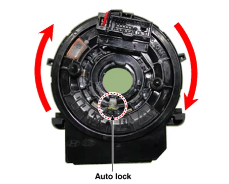
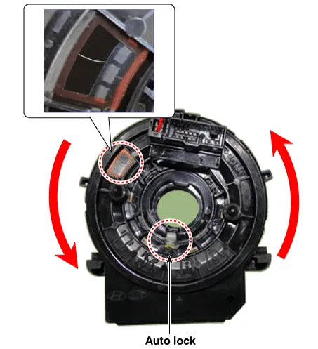
Factory setting for the clock spring is neutral.
|
| 4. |
Manual neutrality setting procedure of clock spring
|
| 5. |
Install the steering wheel column shroud and the steering wheel. (Refer to Steering System - "Steering Wheel") |
| 6. |
Connect the Driver Airbag (DAB) module connector and horn connector, and then install the Driver Airbag (DAB) module on the steering wheel. |
| 7. |
Connect the negative battery terminal. |
| 8. |
After installing the airbag, confirm proper system operation:
|


Other information:
Kia Stinger (CK) 2018-2023 Service Manual: Integrated Body Control Unit (IBU)
Specifications Specifications Items Specifications Rated voltage DC 12 V Operating voltage DC 9 - 16 V Operating temperature -40 - 176°F (-40 - 80°C) Dark current Max. 4.0 mA Components and components location Components Connector Pin Information No.Kia Stinger (CK) 2018-2023 Service Manual: Maintenance services
You should exercise the utmost care to prevent damage to your vehicle and injury to yourself whenever performing any maintenance or inspection procedures. Should you have any doubts concerning the inspection or servicing of your vehicle, we strongly recommend that you have an authorized Kia dealer perform this work. An authorized Kia dealer has factorytrained technicians and genuine Kia parts to service your vehicle properly.Categories
- Manuals Home
- Kia Stinger Owners Manual
- Kia Stinger Service Manual
- New on site
- Most important about car
