Kia Stinger CK: Maintenance / Engine oil
Checking the engine oil level

■ THETA II 2.0L T-GDI Engine (Gasoline)
■ Lambda II PE 3.3L T-GDI Engine (Gasoline)
1. Be sure the vehicle is on level ground.
2. Start the engine and allow it to reach normal operating temperature.
3. Turn the engine off and wait for a few minutes (about 5 minutes) for the oil to return to the oil pan.
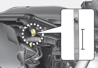
4. Pull the dipstick out, wipe it clean, and reinsert it fully.
WARNING - Radiator hose
Be very careful not to touch the radiator hose when checking or adding the engine oil as it may be hot enough to burn you.
5. Pull the dipstick out again and check the level. The level should be between F and L.
CAUTION - Replacing engine oil
Do not overfill the engine oil. It may damage the engine.
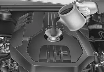
■ THETA II 2.0L T-GDI Engine (Gasoline)
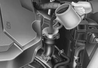
■ Lambda II PE 3.3L T-GDI Engine (Gasoline)
If it is near or at L, add enough oil to bring the level to F. Do not overfill.
Use a funnel to help prevent oil from being spilled on engine components.
Use only the specified engine oil. (Refer to “Recommended lubricants and capacities” in chapter 8.)
Changing the engine oil and filter
Have engine oil and filter changed by an authorized Kia dealer according to the Maintenance Schedule at the beginning of this chapter.
WARNING
Used engine oil may cause irritation or cancer of the skin if left in contact with the skin for prolonged periods of time. Always protect your skin by washing your hands thoroughly with soap and warm water as soon as possible after handling used oil.


Other information:
*1 The system judges a person of adult size as an adult. When a smaller adult sits in the front passenger seat, the system may recognize him/her as a child depending on his/her physique and posture. *2 Do not allow children to ride in the front passenger seat. When a larger child who has outgrown a child restraint system sits in the front passenger seat, the system may recognize him/her as an adult depending upon his/her physique or sitting position.Kia Stinger (CK) 2018-2023 Owner's Manual: Recognizing vehicles
The sensor may be limited when: - The radar or the camera is contaminated with foreign substances. - It heavily rains or snows. - There is electromagnetic interference. - Something in the path of travel deflects the radar waves. - The vehicle in front has a narrow body. (i.e. motor cycle and bicycle) - The driver's view is not clear due to backlight, reflected light, or darkness.Categories
- Manuals Home
- Kia Stinger Owners Manual
- Kia Stinger Service Manual
- New on site
- Most important about car
