Kia Stinger CK: If you have a flat tire / Jack and tools
Contents:
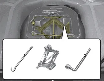
The jack and wheel lug nut wrench are stored in the luggage compartment. Remove the panel indicated in the illustration.
(1) Jack handle
(2) Jack
(3) Wheel lug nut wrench
Jacking instructions
The jack is provided for emergency tire changing only.
To prevent the jack from “rattling” while the vehicle is in motion, store it properly.
Follow jacking instructions to reduce the possibility of personal injury.
WARNING - Tire Jack
Do not place any portion of your body under a vehicle that is only supported by a jack since the vehicle can easily roll off the jack. Use vehicle support stands.
WARNING - Changing tires
Never attempt vehicle repairs in the traffic lanes of a public road or highway.
- Always move the vehicle completely off the road and onto the shoulder before trying to change a tire. The jack should be used on a firm level ground. If you cannot find a firm, level place off the road, call a towing service company for assistance.
- Be sure to use the correct front and rear jacking positions on the vehicle; never use the bumpers or any other part of the vehicle for jack support.
- Do not allow anyone to remain in the vehicle while it is on the jack.
- Make sure any children present are in a secure place away from the road and from the vehicle to be raised with the jack.
WARNING - Running vehicle on jack
Do not start or run the engine of the vehicle while the vehicle is on the jack as this may cause the vehicle to fall off the jack.


Other information:
Repair procedures Inspection Troubleshooting of the speakers When handling the speakers : • Do not cause shock to the speakers by dropping or throwing them. • Be careful not to drop water and oil on the speakers.Repair procedures Removal 1. Drain the coolant. (Refer to Cooling System - "Coolant") 2. Remove the oil filter. (Refer to Lubrication System - "Engine Oil") 3. Disconnect the oil cooler coolant hoses (A). 4. Loosen the mounting bolt (B) and remove the oil cooler assembly (C).Categories
- Manuals Home
- Kia Stinger Owners Manual
- Kia Stinger Service Manual
- New on site
- Most important about car
Contents
