Kia Stinger: Wireless Power Charger (WPC) System / Wireless Power Charging (WPC) Unit
Components and positions
| Components |
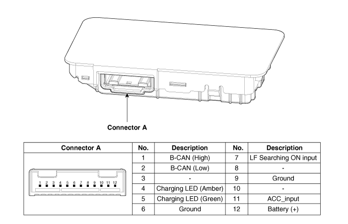
Circuit diagram
| Circuit Diagram |
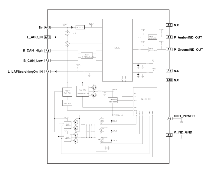
Repair procedures
| Removal |
|
|
| 1. |
Disconnect the negative (-) battery terminal. |
| 2. |
Remove the console complete assembly. (Refer to Body - "Floor Console Assembly") |
| 3. |
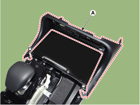
Remove the front cover (A) after loosening the mounting screws.
|
| 4. |
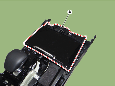
Remove the floor console tray (A) by using a remover.
|
| 5. |
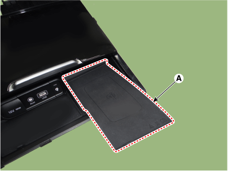
Remove the wireless charging pad (A).
|
| 6. |
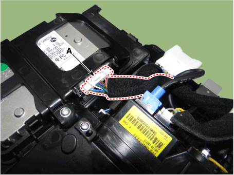
Disconnect the wireless power charging unit connector (A).
|
| 7. |
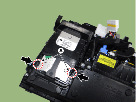
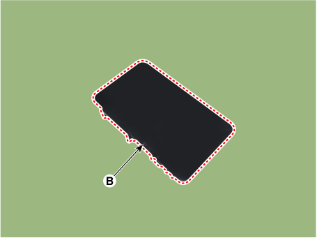
Remove the wireless power charging unit (B) by pressing the fixing hooks (A).
|
| Installation |
| 1. |
Install the wireless power charging unit. |
| 2. |
Connect the wireless power charging unit connector. |
| 3. |
Install the wireless charging pad. |
| 4. |
Install the floor console tray. |
| 5. |
Install the front cover. |
| 6. |
Install the console complete assembly. |
| 7. |
Connect the negative (-) battery terminal. |
| [Diagnosis With KDS] |
| 1. |
The body electrical system can be more quickly diagnosed for troubles by using the vehicle diagnostic system (KDS). KDS provides the following information.
|
| 2. |
To diagnose the vehicle by using the diagnostic equipment, select "vehicle model" and "wireless power charger system" to be inspected. |
| 3. |
To inquire the current status of input/output values, select the "Sensor Data" menu The input/output values of the sensors corresponding to the selected module can be checked. |
| 4. |
To perform forced operation of the selected module input, select "Actuation Test". |
| 5. |
To inquire the cause of trouble for each module by self diagnosis, select 'Diagnostic Trouble Code'. |
 Wireless Power Charger (WPC) System
Specification
Specifications
Item
Specification
Rated voltage
DC 12 V
Operating voltage
DC 9.0 - 16.0 ...
 Wireless Power Charging (WPC) Lamp
Components and positions
Components
Repair procedures
Removal
•
Handling ...
Other information:
Kia Stinger CK 2018-2025 Service Manual: RCV Control Solenoid Valve
Specifications Specification Item Specification Coil Resistance (Ω) 28.3 - 31.1 [20°C(68°F)] Description and operation Description Installed on the intercooler inlet pipe, the RCV (Recirculation Valve ...
Kia Stinger CK 2018-2025 Owners Manual: Automatic turn off function
The interior lights automatically turn off approximately 20 minutes after the ignition switch is turned off, if the lights are in the ON position. If your vehicle is equipped with the theft alarm system, the interior lights automatically turn off approximately 5 seconds after the system is arme ...


