
Kia Stinger CK: Charging System / Alternator
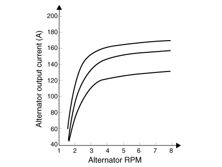
Specifications
| Specification |
▷ 13.5V, 150A
|
Item |
Specification |
|
Rated voltage |
13.5V , 150A |
|
Speed in use |
0 - 18,000 rpm |
|
Pin |
1 |
|
Voltage regulator |
IC Regulator built in type |
|
Default regulated voltage (V) [COM terminal] |
14.39 - 15.43 [-35°C(31°F)] |
|
14.15 - 14.95 [25°C(77°F)] |
|
|
13.23 - 14.49 [140°C(284°F)] |
|
|
Pully Type |
OAP |
Description and operation
| Description |
The Alternator has eight built-in diodes, each rectifying AC current to DC current.
Therefore, DC current appears at alternator "B" terminal.
In addition, the charging voltage of this alternator is regulated by the battery voltage detection system.
The alternator is regulated by the battery voltage detection system.
The main components of the alternator are the rotor, stator, rectifier, capacitor brushes, bearings and V-ribbed belt pulley.
The brush holder contains a built-in electronic voltage regulator.
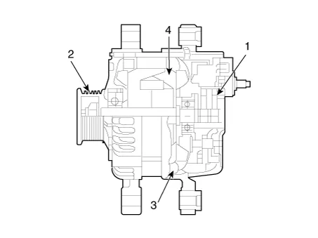
| 1. Brush 2. Drive belt pulley 3. Rotor 4. Stator |
Components and components location
| Components |
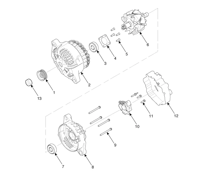
| 1. Pulley 2. Front bracket 3. Front bearing 4. Bearing cover 5. Bearing cover bolt 6. Rotor 7. Rear bearing |
8. Rear bracket8. Shield 9. Through bolt 10. Brush holder assembly 11. Brush holder bolt 12. Rear cover 13. Nut |
Schematic diagrams
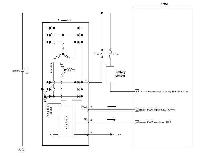
| Circuit Diagram |
|

Repair procedures
| Removal |
| 1. |
Switch "OFF" the ignition and disconnect the negative (-) battery terminal. |
| 2. |
Remove the drive belt. (Refer to Engine Mechanical System - "Drive Belt") |
| 3. |
Disconnect the alternator connector (B), and remove the cable (A) from alternator "B" terminal.
|

| 4. |
Remove the alternator lower bolt and upper bolt (A).
|


| 5. |
Remove the alternator (A).
|


| Installation |
| 1. |
Install in the reverse order of removal. |
| 2. |
Install the drive belt. (Refer to Engine Mechanical System - "Drive Belt") |


Other information:
Kia Stinger (CK) 2018-2023 Service Manual: Engine Oil
Flow diagram Flow Diagram Repair procedures Oil and filter replacement • Prolonged and repeated contact with mineral oil will result in the removal of natural fats from the skin, leading to dryness, irritation and dermatitis.Kia Stinger (CK) 2018-2023 Service Manual: Lane Keeping Assist (LKA) system
The Lane Keeping Assist (LKA) system is designed to detect the lane markers on the road with a front view camera at the front windshield, and assists the driver's steering to help keep the vehicle in the lanes. When the system detects the vehicle straying from its lane, it alerts the driver with a visual and audible warning, while applying a slight countersteering torque, trying to prevent the vehicle from moving out of its lane.Categories
- Manuals Home
- Kia Stinger Owners Manual
- Kia Stinger Service Manual
- New on site
- Most important about car
