Kia Stinger CK: Maintenance / Light bulb position (Side)
Contents:
- Headlamp (LED type) replacement (Headlamp Type B)
- Side marker bulb replacement (Headlamp Type A)
- Position lamp + DRL (LED type) bulb replacement (Headlamp Type A)
- Headlamp (Low/High beam) bulb replacement (Headlamp Type A)
- Stop and tail lamp (LED type) bulb replacement
- Rear side marker (LED type) bulb replacement
- Rear turn signal lamp (LED type) bulb replacement
- Rear turn signal lamp (bulb type) bulb replacement
- Back-up lamp bulb replacement
- High mounted stop lamp (LED type) bulb replacement
- License plate lamp (LED type) bulb replacement
- Side repeater lamp (LED type) bulb replacement
- Map lamp (LED type) bulb replacement
- Vanity mirror lamp (LED type) bulb replacement
- Room lamp (LED type) bulb replacement
- Glove box lamp (LED type) bulb replacement
- Luggage room lamp (LED type) bulb replacement
■ Side repeater lamp
(1) Side repeater lamp (LED type)
Headlamp (LED type) replacement (Headlamp Type B)

■ Head lamp - Type B
If the Low/High beam lamp (1, 2), Front turn signal lamp (3), Day time running lamp/Position lamp (4), and/or Side marker (5) do not operate, have the vehicle checked by an authorized Kia dealer.
The LED lamps cannot be replaced as a single component because they are part of an integrated unit. The LED lamps have to be replaced with the unit.
A skilled technician should check or repair the head lamp (LED), for it may damage related parts of the vehicle.
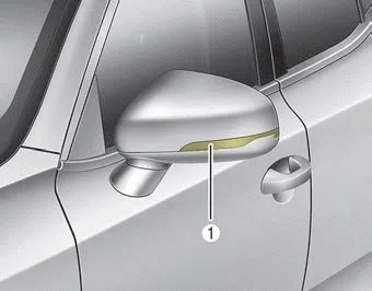
Side marker bulb replacement (Headlamp Type A)

■ Head lamp - Type A
If the side marker (1) does not operate, have the vehicle checked by an authorized Kia dealer.
A skilled technician should check or repair the side marker, for it may damage related parts of the vehicle.
Position lamp + DRL (LED type) bulb replacement (Headlamp Type A)

■ Head lamp - Type A
If the position lamp + DRL (LED) (1) does not operate, have the vehicle checked by an authorized Kia dealer.
The LED lamps cannot be replaced as a single component because they are part of an integrated unit. The LED lamps have to be replaced with the unit.
A skilled technician should check or repair the position lamp + DRL (LED), for it may damage related parts of the vehicle.
Headlamp (Low/High beam) bulb replacement (Headlamp Type A) ➤
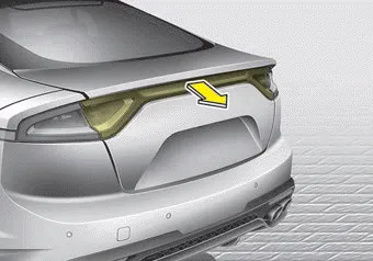
Stop and tail lamp (LED type) bulb replacement

If the stop and tail lamp (LED) (1, 2) does not operate, have the vehicle checked by an authorized Kia dealer.
The LED lamps cannot be replaced as a single component because they are part of an integrated unit. The LED lamps have to be replaced with the unit.
A skilled technician should check or repair the stop and tail lamp (LED), for it may damage related parts of the vehicle.
Rear side marker (LED type) bulb replacement

If the rear side marker (LED) (1) does not operate, have the vehicle checked by an authorized Kia dealer.
The LED lamps cannot be replaced as a single component because they are part of an integrated unit. The LED lamps have to be replaced with the unit.
A skilled technician should check or repair the rear side marker (LED), for it may damage related parts of the vehicle.
Rear turn signal lamp (LED type) bulb replacement

If the rear turn signal lamp (LED) (1), does not operate, have the vehicle checked by an authorized Kia dealer.
The LED lamps cannot be replaced as a single component because they are part of an integrated unit. The LED lamps have to be replaced with the unit.
A skilled technician should check or repair the rear turn signal lamp (LED), for it may damage related parts of the vehicle.
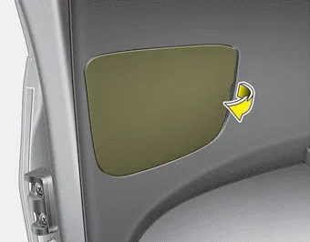
Rear turn signal lamp (bulb type) bulb replacement

1. Open the liftgate.
2. Open the service cover.


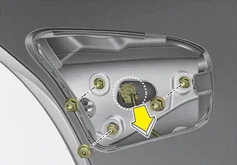
3. Loosen the light assembly retaining screws with a cross-tip screwdriver or spanner.
4. Remove the rear combination lamp assembly from the body of the vehicle.
5. Disconnect the rear combination lamp connector.

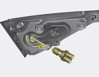
6. Remove the socket from the assembly by turning the socket counterclockwise until the tabs on the socket align with the slots on the assembly.
7. Remove the bulb from the socket by pressing it in and rotating it counterclockwise until the tabs on the bulb align with the slots in the socket. Pull the bulb out of the socket.
8. Insert a new bulb by inserting it into the socket and rotating it until it locks into place.
9. Install the socket in the assembly by aligning the tabs on the socket with the slots in the assembly. Push the socket into the assembly and turn the socket clockwise.
10. Install the rear combination lamp assembly to the body of the vehicle.
11. Install the service cover.
Back-up lamp bulb replacement
1. Open the liftgate.
2. Remove the service cover of both side (drive side and passenger side).
3. Remove the nuts from rear combination lamp of both side (drive side and passenger side).
4. Disconnect the connector from rear combination lamp of both side (drive side and passenger side).
5. Remove the rear combination lamp assembly from the body of the vehicle.
6. Remove the socket from the assembly by turning the socket counterclockwise until the tabs on the socket align with the slots on the assembly.
7. Remove the bulb from the socket by pressing it in and rotating it counterclockwise until the tabs on the bulb align with the slots in the socket. Pull the bulb out of the socket.
8. Insert a new bulb by inserting it into the socket and rotating it until it locks into place.
9. Install the socket in the assembly by aligning the tabs on the socket with the slots in the assembly. Push the socket into the assembly and turn the socket clockwise.
10. Install the rear combination lamp assembly to the body of the vehicle.
11. Install the service cover by putting it into the service hole.
High mounted stop lamp (LED type) bulb replacement

If the high mounted stop lamp (LED) (1) does not operate, have the vehicle checked by an authorized Kia dealer.
The LED lamps cannot be replaced as a single component because they are part of an integrated unit. The LED lamps have to be replaced with the unit.
A skilled technician should check or repair the high mounted stop lamp (LED), for it may damage related parts of the vehicle.
License plate lamp (LED type) bulb replacement

If the license plate lamp (LED) (1) does not operate, have the vehicle checked by an authorized Kia dealer.
The LED lamps cannot be replaced as a single component because they are part of an integrated unit. The LED lamps have to be replaced with the unit.
A skilled technician should check or repair the license plate lamp (LED), for it may damage related parts of the vehicle.
Side repeater lamp (LED type) bulb replacement

If the side repeater lamp (LED) (1) does not operate, have the vehicle checked by an authorized Kia dealer.
The LED lamps cannot be replaced as a single component because they are part of an integrated unit. The LED lamps have to be replaced with the unit.
A skilled technician should check or repair the side repeater lamp (LED), for it may damage related parts of the vehicle.
Map lamp (LED type) bulb replacement

If the map lamp (LED) (1) does not operate, have the vehicle checked by an authorized Kia dealer.
The LED lamps cannot be replaced as a single component because they are part of an integrated unit. The LED lamps have to be replaced with the unit.
A skilled technician should check or repair the map lamp (LED), for it may damage related parts of the vehicle.
Vanity mirror lamp (LED type) bulb replacement

If the vanity mirror lamp (LED) (1) does not operate, have the vehicle checked by an authorized Kia dealer.
The LED lamps cannot be replaced as a single component because they are part of an integrated unit. The LED lamps have to be replaced with the unit.
A skilled technician should check or repair the vanity mirror lamp (LED), for it may damage related parts of the vehicle.
Room lamp (LED type) bulb replacement

If the room lamp (LED) (1) does not operate, have the vehicle checked by an authorized Kia dealer.
The LED lamps cannot be replaced as a single component because they are part of an integrated unit. The LED lamps have to be replaced with the unit.
A skilled technician should check or repair the room lamp (LED), for it may damage related parts of the vehicle.
Glove box lamp (LED type) bulb replacement

If the glove box lamp (LED) (1) does not operate, have the vehicle checked by an authorized Kia dealer.
The LED lamps cannot be replaced as a single component because they are part of an integrated unit. The LED lamps have to be replaced with the unit.
A skilled technician should check or repair the glove box lamp (LED), for it may damage related parts of the vehicle.
Luggage room lamp (LED type) bulb replacement

If the luggage room lamp (LED) (1) does not operate, have the vehicle checked by an authorized Kia dealer.
The LED lamps cannot be replaced as a single component because they are part of an integrated unit. The LED lamps have to be replaced with the unit.
A skilled technician should check or repair the luggage room lamp (LED), for it may damage related parts of the vehicle.


Other information:
Kia Stinger (CK) 2018-2023 Owner's Manual: ISG (Idle Stop and Go) system
Your vehicle may be equipped with the ISG system, which reduces fuel consumption by automatically shutting down the engine, when the vehicle is at a standstill. (For example : red light, stop sign and traffic jam) The engine starts automatically as soon as the starting conditions are met. The ISG system is ON whenever the engine is running. ✽ NOTICE When the engine automatically starts by the ISG system, some warning lights (ABS, ESC, ESC OFF, EPS or Parking brake warning light) may turn on for a few seconds.Kia Stinger (CK) 2018-2023 Owner's Manual: Emission Control System
Components and components location Components Location 1. PCV Valve 2. Canister 3. Purge control solenoid valve (PCSV) 4. Fuel tank air filter 5. Catalytic converter (WCC) 6. Vapor hose (Canister ↔ Intake Manifold) 7. Vapor Hose (Canister ↔ Fuel Tank) 8. Ventilation Hose (Canister ↔ Atmosphere) 1.Categories
- Manuals Home
- Kia Stinger Owners Manual
- Kia Stinger Service Manual
- Headlamp (LED type) replacement (Headlamp Type B)
- Side marker bulb replacement (Headlamp Type A)
- Position lamp + DRL (LED type) bulb replacement (Headlamp Type A)
- Headlamp (Low/High beam) bulb replacement (Headlamp Type A)
- Stop and tail lamp (LED type) bulb replacement
- Rear side marker (LED type) bulb replacement
- Rear turn signal lamp (LED type) bulb replacement
- Rear turn signal lamp (bulb type) bulb replacement
- Back-up lamp bulb replacement
- High mounted stop lamp (LED type) bulb replacement
- License plate lamp (LED type) bulb replacement
- Side repeater lamp (LED type) bulb replacement
- Map lamp (LED type) bulb replacement
- Vanity mirror lamp (LED type) bulb replacement
- Room lamp (LED type) bulb replacement
- Glove box lamp (LED type) bulb replacement
- Luggage room lamp (LED type) bulb replacement
- New on site
- Most important about car
Contents
