Kia Stinger CK: Emission Control System / Evaporative Emission Control System
Contents:
Description and operation
| Description |
Evaporative Emission Control System prevents fuel vapor stored in fuel tank from vaporizing into the atmosphere. When the fuel evaporates from the fuel tank, the vapor passes through vent hoses or tubes into canister filled with charcoal and the canister temporarily holds the vapor in the charcoal.
If ECM determines to draw the gathered vapor into the combustion chambers at certain operating conditions, it will use vacuum in the intake manifold to move it.
Schematic diagrams
| Schematic Diagram |
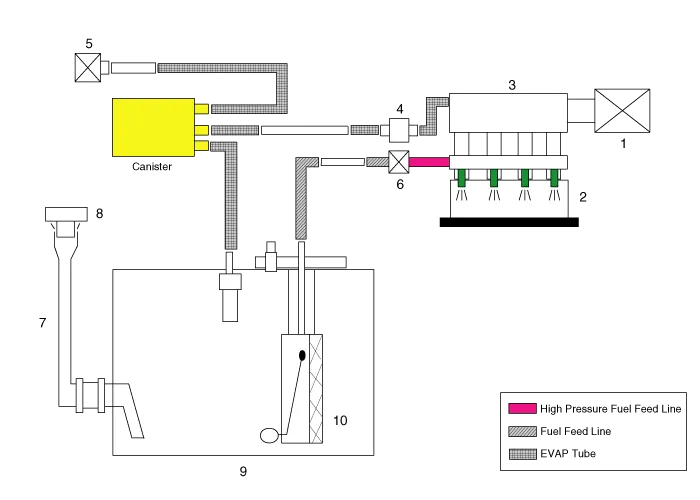
| 1. Air cleaner 2. Delivery pipe & injector 3. Engine 4. Purge control solenoid valve (PCSV) 5. Fuel tank air filter |
6. High pressure fuel pump
7. Fuel filler hose 8. Fuel filler cap 9. Fuel tank 10. Low pressure fuel pump |
Canister
Canister is filled with charcoal and absorbs evaporated vapor in fuel tank. The gathered fuel vapor in canister is drawn into the intake manifold by the ECM/PCM when appropriate conditions are met.
Purge Control Solenoid Valve (PCSV)
Purge Control Solenoid Valve (PCSV) is installed in the passage connecting canister and intake manifold. It is a duty cycle control type solenoid valve operated by ECM/PCM signal.
To draw the absorbed vapor into the intake manifold, the ECM/PCM will open the PCSV, otherwise the passage remains closed.
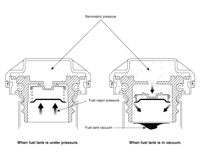
Fuel Filler Cap
A ratchet tightening device on the threaded fuel filler cap reduces the chances of incorrect installation, which would seal the fuel filler. After the gasket on the fuel filler cap and the fill neck flange contact each other, the ratchet produces a loud clicking noise indicating that the seal has been set.
Canister ➤
Purge Control Solenoid Valve (PCSV) ➤
Fuel Filler Cap
Description and operation
| Description |
A ratchet tightening device on the threaded fuel filler cap reduces the chances of incorrect installation, which seals the fuel filler. After the gaskets on the fuel filler cap and the filler neck flange contact each other, the ratchet produces a loud clicking noise indicating that the seal has been set.
Fuel Tank Air Filter
Repair procedures
| Removal |
| 1. |
Switch "OFF" the ignition and disconnect the negative (-) battery terminal. |
| 2. |
Remove the rear-left wheel & tire and wheel house cover. |
| 3. |
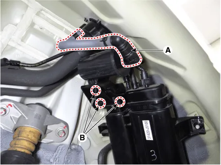
Disconnect the vent hose quick-connector (A). |
| 4. |
Remove the fuel tank air filter after removing the bolts (B).
|
| Installation |
| 1. |
Install in the reverse order of removal. |


Other information:
Kia Stinger (CK) 2018-2023 Service Manual: Turn Signal Lamp
Repair procedures Removal Door Mirror Turn Signal Lamp 1. Disconnect the negative (-) battery terminal. 2. Remove the outside rear view mirror. (Refer to Body - "Outside Rear View Mirror") 3. Remove mirror (A) to the direction as shown in the picture using (-) screw driver.Kia Stinger (CK) 2018-2023 Service Manual: Fuse/relay panel description
■ Driver’s side fuse panel ■ Engine compartment fuse panel ■ Rear fuse box panel ■ Battery box fuse panel Inside the fuse/relay panel covers, you can find the fuse/relay label describing fuse/relay name and capacity. ✽ NOTICE Not all fuse panel descriptions in this manual may be applicable to your vehicle. It is accurate at the time of printing.Categories
- Manuals Home
- Kia Stinger Owners Manual
- Kia Stinger Service Manual
- New on site
- Most important about car
Contents
