Kia Stinger CK: What to do in an emergency / Towing
Contents:
Towing service ➤
Removable towing hook
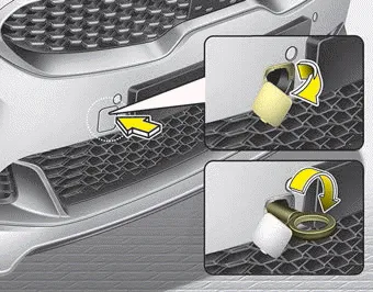
1. Open the liftgate, and remove the towing hook from the tool case.
2. Remove the hole cover pressing the right side part or lower part of the cover on the bumper.
3. Install the towing hook by turning it clockwise into the hole until it is fully secured.
4. Remove the towing hook and install the cover after use.
Emergency towing ➤


Other information:
Kia Stinger (CK) 2018-2023 Owner's Manual: Tire replacement
If the tire is worn evenly, a tread wear Indicator (A) will appear as a solid band across the tread. This shows there is less than 1.6 mm (1/16 inch) of tread left on the tire. Replace the tire when this happens. Do not wait for the band to appear across the entire tread before replacing the tire. The ABS (Anti-lock Brake System) works by comparing the speed of the wheels.Kia Stinger (CK) 2018-2023 Owner's Manual: Front Suspension System
Components and components location Components Location 1. Front stabilizer bar 2. Steering gear box 3. Front strut assembly 4. Front axle 5. Compression arm 6. Lateral armCategories
- Manuals Home
- Kia Stinger Owners Manual
- Kia Stinger Service Manual
- New on site
- Most important about car
Contents

Copyright © 2026 www.kstinger.com 0.0075