Kia Stinger CK: Maintenance / Battery
Contents:
Battery replacement
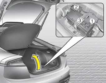
The battery is in the trunk under the compartment cover.
When replacing the battery, disconnect the negative (-) cable (1) and remove the positive (+) battery fuse box (2).
Remove the battery mounting bracket (3).
WARNING - Touching metal surfaces in the trunk under the compartment cover
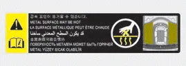
Do not touch metal surfaces in the trunk under the compartment cover while the engine is operating or hot. Doing so could result in serious personal injury. Turn the engine off and wait until it cools down or wear gloves to replace the battery from the luggage room.
For best battery service ➤
Recharging the battery
Your vehicle has a maintenance-free, calcium-based battery.
- If the battery becomes discharged in a short time (because, for example, the headlamps or interior lamps were left on while the vehicle was not in use), recharge it by slow charging (trickle) for 10 hours.
- If the battery gradually discharges because of high electric load while the vehicle is being used, recharge it at 20-30A for two hours.
When recharging the battery, observe the following precautions:
- The battery must be removed from the vehicle and placed in an area with good ventilation.
- Do not allow cigarettes, sparks, or flame near the battery.
- Watch the battery during charging, and stop or reduce the charging rate if the battery cells begin gassing (boiling) violently or if the temperature of the electrolyte of any cell exceeds 49°C (120°F).
- Wear eye protection when checking the battery during charging.
- Disconnect the battery charger in the following order.
- 1. Turn off the battery charger main switch.
2. Unhook the negative clamp from the negative battery terminal.
3. Unhook the positive clamp from the positive battery terminal. - Before performing maintenance or recharging the battery, turn off all accessories and stop the engine.
- The negative battery cable must be removed first and installed last when the battery is disconnected.
Reset items
Items should be reset after the battery has been discharged or the battery has been disconnected.
- Auto up/down window
- Sunroof
- Trip computer
- Climate control system
- Driver position memory system


Other information:
Kia Stinger (CK) 2018-2023 Owner's Manual: Power Door Lock Switch
Repair procedures Inspection Diagnosis With KDS 1. The body electrical system can be quickly diagnosed for failed parts by using vehicle diagnostic system (KDS). The diagnostic system (KDS) provides the following information. (1) Self diagnosis : Checks and displays the failure code (DTC) (2) Current data : Checks the system input/output data state (3) Actuation test : Checks the system operating condition (4) Additional function : Other controls such as the system option and zero point 2.Kia Stinger (CK) 2018-2023 Owner's Manual: Curtain Airbag (CAB) Module
Description and operation Description Installed inside the headliner, the curtain airbags (CAB) protect the driver and passengers from danger in the eThe SRSCM determines deployment of curtain airbag based on side impact sensor (SIS) signal.The SRSCM determines deployment of curtain airbag by using side impact sensor (SIS) signal.Categories
- Manuals Home
- Kia Stinger Owners Manual
- Kia Stinger Service Manual
- New on site
- Most important about car
Contents
