Kia Stinger CK: ESP(Electronic Stability Program) System / ESP Control Module
Components and components location
| Components |
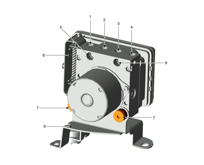
| 1. FR 2. RL 3. RR 4. FL 5. MC2 (SEC) |
6. MC1 (PRI) 7. Damper 8. ESP control module connector 9. ESP control module bracket |
Repair procedures
| Removal |
[LHD]
| 1. |
Turn ignition switch OFF and disconnect the negative (-) battery cable. |
| 2. |
Separate the engine room relay block. (Refer to Body Electrical System - "Relay box (Engine compartment)") |
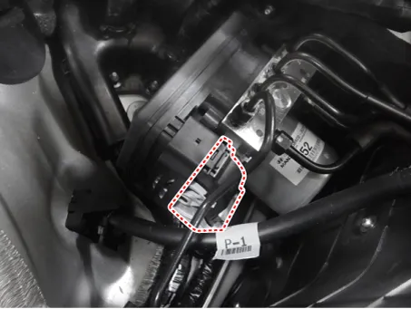
| 3. |
Disconnect the ESP connector.
|
| 4. |
Loosen the ESP brake tube flare nuts.
|
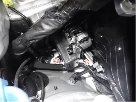
| 5. |
Loosen the ESP bracket bolts and then remove the ESP.
|

[RHD]
| 1. |
Turn ignition switch OFF and disconnect the negative (-) battery cable. |
| 2. |
Remove the air cleaner. D 2.2 R VGT (Refer to Engine Mechanical System - "Air Cleaner") D 2.2 R VGT (Enhanced Euro 6) (Refer to Engine Mechanical System - "Air Cleaner") G 2.0 T-GDI (Refer to Engine Mechanical System - "Air Cleaner") G 3.3 T-GDI (Refer to Engine Mechanical System - "Air Cleaner") |
| 3. |
Recover the refrigerant. (Refer to Heating, Ventilation and Air conditioning - "Repair procedures") |
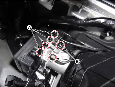
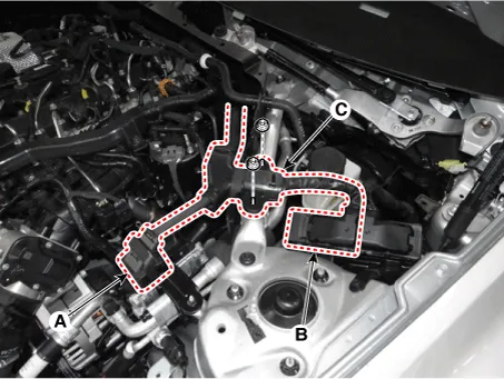
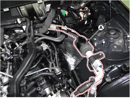
| 4. |
Disconnect the discharge line (A) and suction line (B).
|

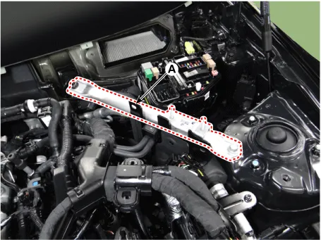
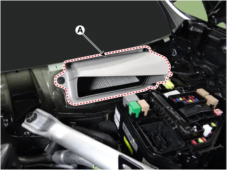
| 5. |
Remove the LH hood sealing cover (A).
|
| 6. |
Disconnect the wiring connector and harness from the engine room.
|
| 7. |
Remove the engine control module (ECM). D 2.2 R VGT (Refer to Engine Control /Fuel System - "Engine Control Module (ECM)") D 2.2 R VGT (Enhanced Euro 6) (Refer to Engine Control /Fuel System - "Engine Control Module (ECM)") G 2.0 T-GDI (Refer to Engine Control /Fuel System - "Engine Control Module (ECM)") G 3.3 T-GDI (Refer to Engine Control /Fuel System - "Engine Control Module (ECM)") |
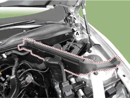
| 8. |
Remove the cowl shock absorber housing bar (A).
|
| 9. |
Remove the transmission control unit (TCM). D 2.2 R VGT (Refer to Automatic Transmission System - "Transmission Control Module (TCM)") D 2.2 R VGT (Enhanced Euro 6) (Refer to Automatic Transmission System - "Transmission Control Module (TCM)") G 2.0 T-GDI (Refer to Automatic Transmission System - "Transmission Control Module (TCM)") G 3.3 T-GDI (Refer to Automatic Transmission System - "Transmission Control Module (TCM)") |
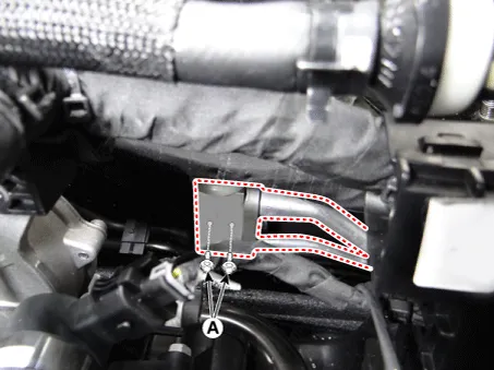
| 10. |
Loosen the suction & liquid tube mounting bolts (A).
|
| 11. |
Remove the suction & liquid tube assembly (A).
|
| 12. |
Remove the air blower duct (A).
|
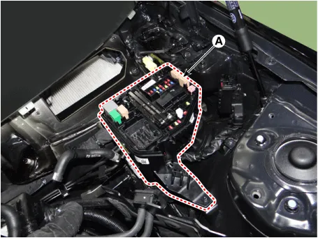
| 13. |
Separate the engine room relay box (A).
|
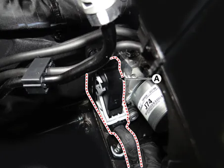
| 14. |
Disconnect the ESP connector (A).
|
| 15. |
Loosen the ESP brake tube flare nuts.
|
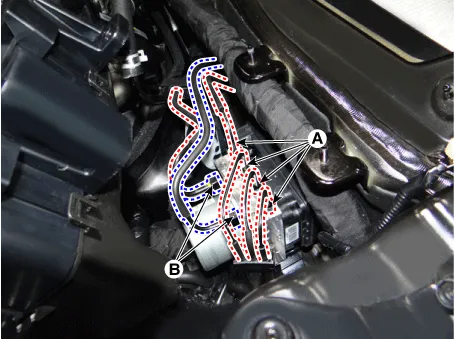
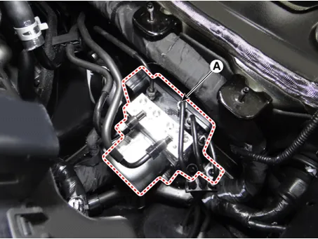
| 16. |
Remove the ESP control module (A).
|
| Installation |
| 1. |
Install in the reverse order of removal. |
| 2. |
After installation, bleed the brake system. (Refer to Brake system - "Brake Bleeding Procedures") |
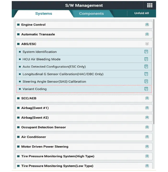
| Diagnostic procedure by using diagnostic device |
Perform diagnostic procedure by using diagnostic device as shown below:
Connect self-diagnosis connector (16pins) located under the driver side crash pad to self-diagnosis device, and then turn the self-diagnosis device after key is ON.
Select the "vehicle model" and "ESP/ESC" on KDS vehicle selection screen, then select OK.
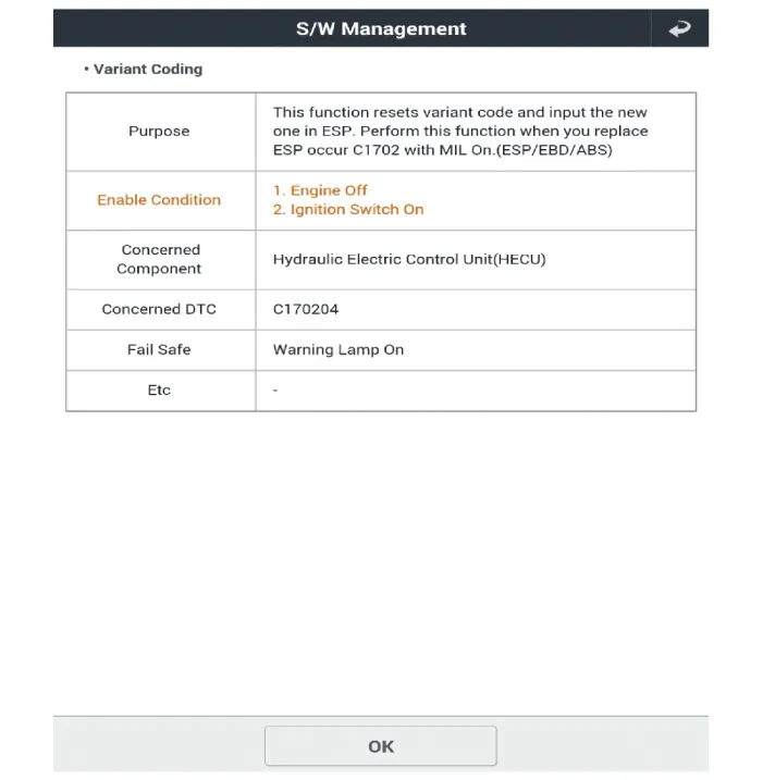
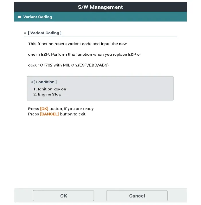
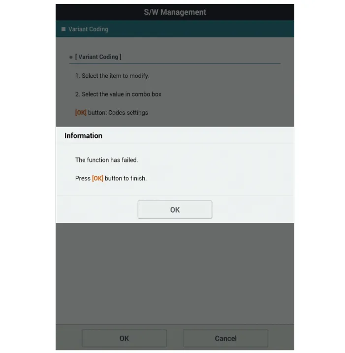
| [Variant Code Reset] |

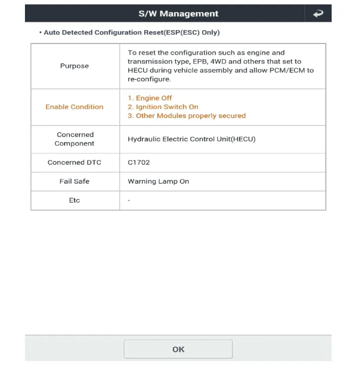
| [Auto Detected Sensor Calibration] |
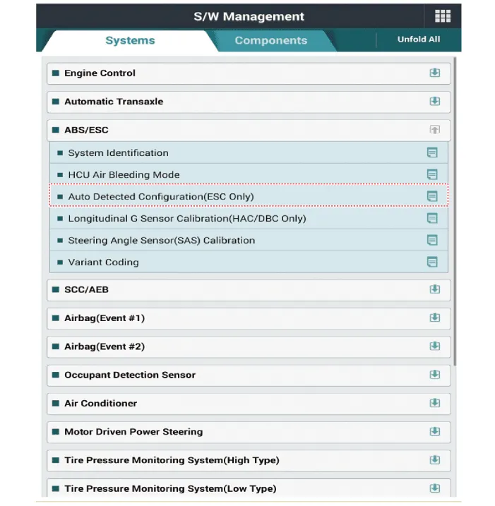
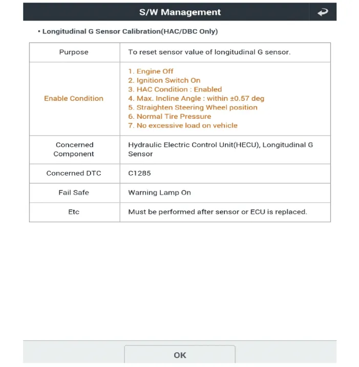
| [Longitudinal G Sensor Calibration] |


Other information:
Kia Stinger (CK) 2018-2023 Service Manual: Shift to P to edit settings
This warning message appears if you try to adjust the User Settings while driving. For your safety, change the User Settings after parking the vehicle, applying the parking brake and pressing the parking “P” button. Head-Up Display (HUD) Enable Head-Up Display : If this item is checked, Head-Up Display will be activated. Display Height : Adjust the height of the HUD image on the windshield glass.Kia Stinger (CK) 2018-2023 Service Manual: Climate Control Air Filter
Description and operation Description Located in the blower unit, the climate control air filter eliminates foreign materials and odor. The particle filter performs the roles of an odor filter as well as a conventional dust filter to ensure pleasant interior environment. Repair procedures Replacement 1. Remove the stopper (B) from the glove box (A).Categories
- Manuals Home
- Kia Stinger Owners Manual
- Kia Stinger Service Manual
- New on site
- Most important about car
