Kia Stinger CK: ESP(Electronic Stability Program) System / Front Wheel Speed Sensor
Repair procedures
| Removal |
| [2WD] |
| 1. |
Remove wheel nuts, wheel and tire (A) from front hub.
|


| 2. |
Disconnect the front wheel speed sensor connector from the front axle.
|

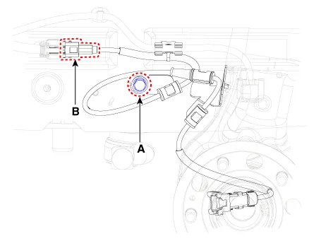
| 3. |
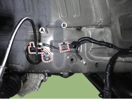
Loosen the wheel speed sensor bracket bolt (A), and then disconnect the wheel speed sensor connector (B).
|
| 4. |
Install in the reverse order of removal. |
| [AWD] |
| 1. |
Remove wheel nuts, wheel and tire (A) from front hub.
|
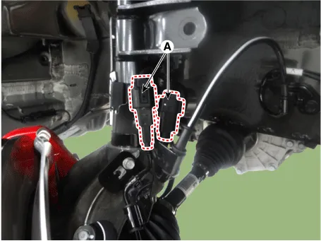
| 2. |
Loosen the wheel speed sensor bolt and then remove the wheel speed sensor (A).
|
| 3. |
Remove the wheel speed sensor bracket.
|
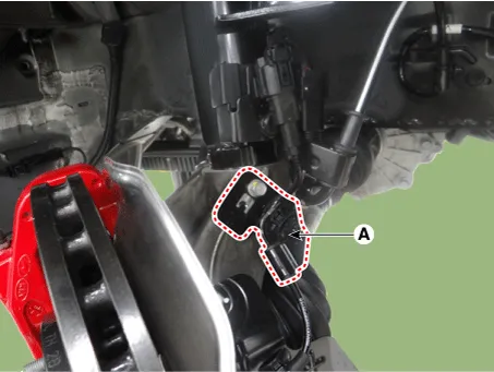
| 4. |
Disconnect the ECS connector (A) and then remove the bracket.
|
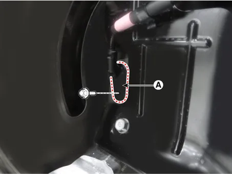
| 5. |
Remove the bracket (A) and the remove the connector (B).
|
| 6. |
Install in the reverse order of removal. |
| Inspection |
| 1. |
Measure the output voltage between the terminal of the wheel speed sensor and the body ground.
|
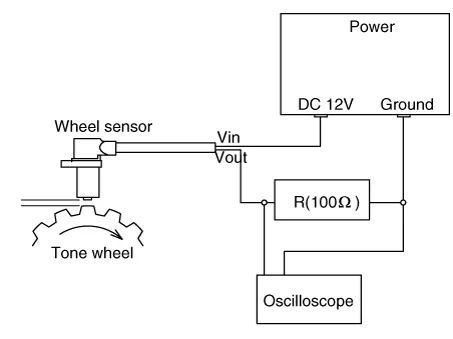
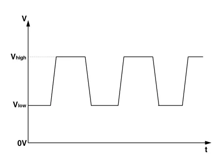
| 2. |
Compare the change of the output voltage of the wheel speed sensor to the normal change of the output voltage as shown below.
|


Other information:
Kia Stinger (CK) 2018-2023 Service Manual: Around View Monitor (AVM) Unit
Components and components location Components Schematic diagrams Circuit Diagram Repair procedures Removal Put on gloves to protect your hands. • When prying with a flat-tip screwdriver or use a prying trim tool, wrap it with protective tape, and apply protective tape around the related parts, to prevent damage.Kia Stinger (CK) 2018-2023 Service Manual: Tail Gate Back Panel
Repair procedures Replacement • Use a plastic panel removal tool to remove interior trim pieces without marring the surface. • Take care not to bend or scratch the trim and panels. 1.Categories
- Manuals Home
- Kia Stinger Owners Manual
- Kia Stinger Service Manual
- New on site
- Most important about car
