Kia Stinger CK: ESP(Electronic Stability Program) System / Rear Wheel Speed Sensor
Repair procedures
| Removal |
| [NON ECS] |
| 1. |
Remove wheel nuts, wheel and tire (A) from hub.
|


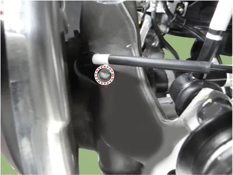
| 2. |
Loosen the rear wheel speed sensor bolt and then remove the rear wheel speed sensor.
|
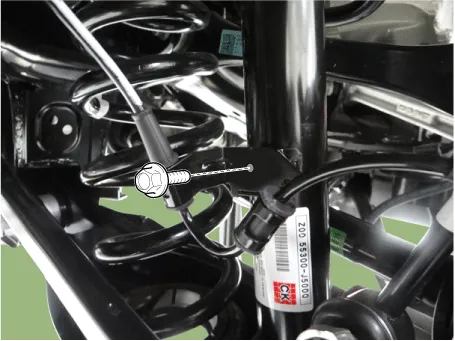
| 3. |
Loosen the rear wheel speed sensor bracket bolt.
|
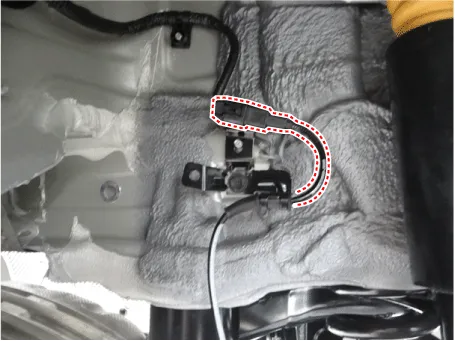
| 4. |
Disconnect the rear wheel speed sensor connector.
|
| 5. |
Install in the reverse order of removal. |
| [ECS] |
| 1. |
Remove wheel nuts, wheel and tire (A) from hub.
|
| 2. |
Loosen the rear wheel speed sensor bolt and then remove the rear wheel speed sensor.
|
| 3. |
Disconnect the ECS connector (A). |
| 4. |
Loosen the ECS connector bracket bolt (B).
|

| 5. |
Disconnect the rear wheel speed sensor connector.
|
| 6. |
Install in the reverse order of removal. |
| Inspection |
| 1. |
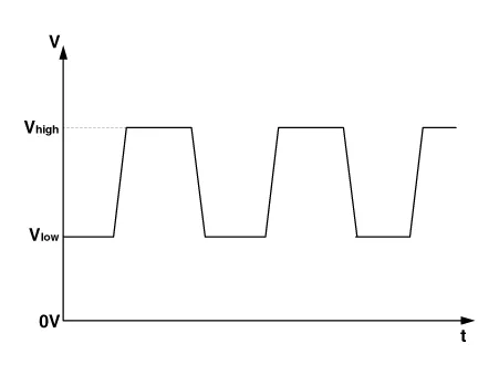
Measure the output voltage between the terminal of the wheel speed sensor and the body ground.
|
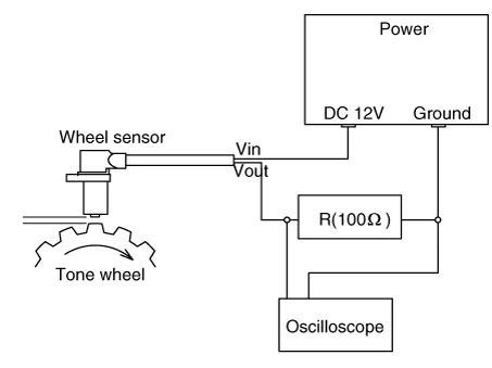
| 2. |
Compare the change of the output voltage of the wheel speed sensor to the normal change of the output voltage as shown below.
|


Other information:
Components and components location Component Location 1. Driver power window switch 2. Assist power window switch 3 . Integrated central control unit (ICU) 4 . Door lock knob 5 . Tailgate actuator 6. Door latch assembly 7 . Door lock/unlock switch 8 . Rear left power window switch 9 .Components and components location Component Location 1. Wide sunroof 2. Wide sunroof switch 3. Roller blind motor & slave controller 4. Glass motor & controller Schematic diagrams Circuit Diagram No. Sunroof wiring connector (Vehicle side) Glass motor (Master) Blind motor (Slave)Categories
- Manuals Home
- Kia Stinger Owners Manual
- Kia Stinger Service Manual
- New on site
- Most important about car
