Kia Stinger CK: Charging System / DC DC converter
Components and components location
| Components Location |

Description and operation
| Description |
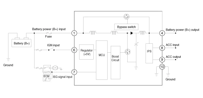
Due to the considerably more frequent occurrence of starting operations, the electrical load that occurs often leads to voltage dips in the vehicle network.In order to stabilize the power supply for certain voltage-sensitive electrical components, a DC/DC converter is used in conjunction with the ISG function.The DC DC converter supplies the relay with a voltage that also remains constant during the starting operation.
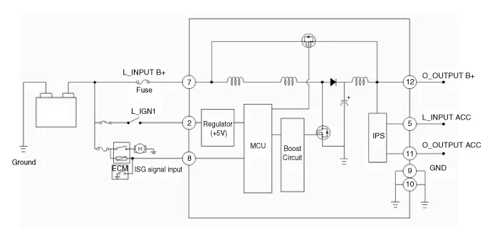
The DC/DC converter is fitted at the behind of the glove box.Via the test leads for input voltage and the start relay , the electronics decide whether the power is supplied to the output via the bypass or the DC/DC converter.In the bypass mode, the on-board supply voltage is not fed across the DC/DC converter, rather is transferred directly to the outputs. In the booster phase, the vehicle voltage is adapted.

Schematic diagrams
| Circuit Diagram |
| [200W] |
| [400W] |
| Terminal Function |
| [200W] |

|
PIn. |
Description |
PIn. |
Description |
|
1 |
Battery power (B+) input |
7 |
ISG signal input |
|
2 |
- |
8 |
ACC input |
|
3 |
- |
9 |
ACC output |
|
4 |
Battery power (B+) output |
10 |
Ground |
|
5 |
- |
11 |
- |
|
6 |
IGN1 input |
|
|
| [400W] |

|
PIn. |
Description |
PIn. |
Description |
|
1 |
- |
7 |
Battery power (B+) input |
|
2 |
IGN1 input |
8 |
ISG signal input |
|
3 |
- |
9 |
Ground |
|
4 |
- |
10 |
Ground |
|
5 |
ACC input |
11 |
ACC output |
|
6 |
- |
12 |
Battery power (B+) output |
Repair procedures
| Removal |
| [200W] |
| 1. |
Switch "OFF" the ignition and disconnect the negative (-) battery terminal. |
| 2. |
Remove the glove box housing. (Refer to Body (Interior and Exterior) - "Glove Box Housing") |
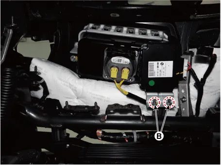
| 3. |
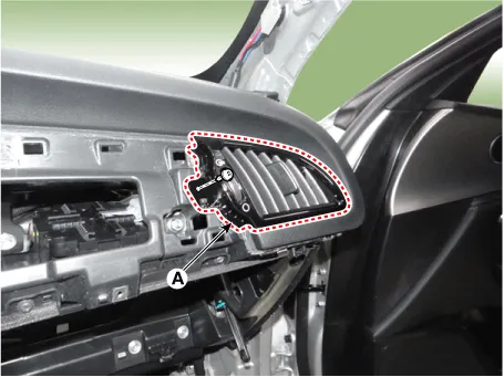
Remove the [RH] side air bant duct (A) after loosening the mounting screw.
|
| 4. |
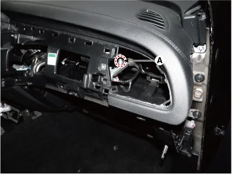
Remove the DC/DC converter after loosening the mounting bolt (A) and nut(B).
|
| [400W] |
| 1. |
Switch "OFF" the ignition and disconnect the negative (-) battery terminal. |
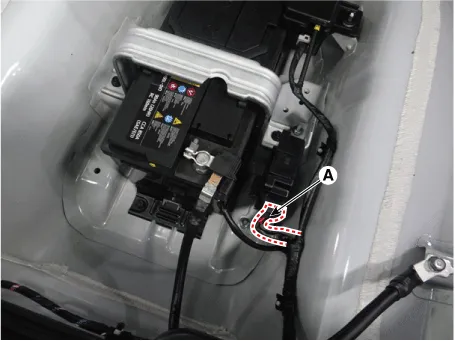
| 2. |
Disconnect the DC/DC converter connector (A).
|
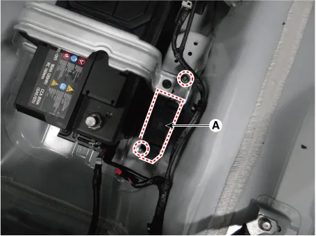
| 3. |
Remove the DC/DC converter (A) after loosening the mounting nuts.
|
| Installation |
After reconnecting the battery negative cable, ISG function does not operates until the system is stabilized, about 4 hours. If disconnecting the negative (-) battery cable from the battery during repair work for the vehicle equipped with AMS function, Battery sensor recalibration procedure should be performed after finishing the repair work. |

| 1. |
Install in the reverse order of removal. |


Other information:
Kia Stinger (CK) 2018-2023 Service Manual: Fuel Filter (For Diesel engine only)
Repair procedures Removal 1. Switch "OFF" the ignition and disconnect the negative (-) battery terminal. 2. Remove the engine cover (A). 3. Disconnect the water sensor connector & fuel heater connector (A), fuel pressure sensor connector (B). 4.Repair procedures Inspection Troubleshooting of the speakers When handling the speakers : • Do not cause shock to the speakers by dropping or throwing them. • Be careful not to drop water and oil on the speakers.Categories
- Manuals Home
- Kia Stinger Owners Manual
- Kia Stinger Service Manual
- New on site
- Most important about car
