Kia Stinger CK: Chassis / Disc Brakes and Pads
Repair procedures
| Inspection |
Check the pads for excessive wear, discs for run out and wear, and calipers for fluid leakage.
| Front Brake |
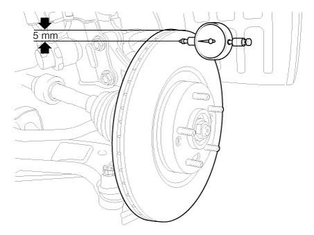
Front brake disc thickness check
| 1. |
Check the brake pads for wear and fade. |
| 2. |
Check the brake disc for damage and cracks. |
| 3. |
Remove all rust and contamination from the surface, and measure the disc thickness at 8 points, at least, of same distance (5mm) from the brake disc outer circle.
|
| 4. |
If wear exceeds the limit, replace the discs and pad assembly left and right of the vehicle. |
Front Brake Pad Check
| 1. |
Check the pad wear. Measure the pad thickness and replace it, if it is less than the specified value.
|
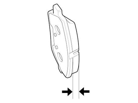
| 2. |
Check that grease is applied, to sliding contact points and the pad and backing metal for damage. |
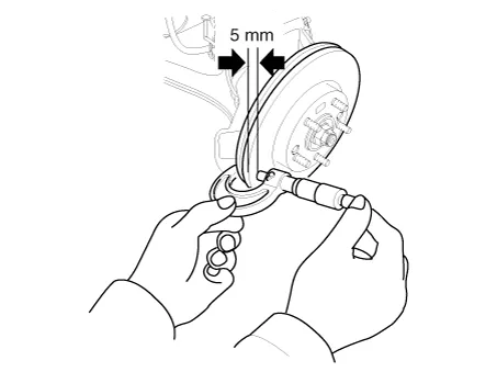
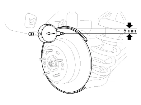
Front brake disc runout check
| 1. |
Place a dial gauge about 5mm (0.2 in.) from the outer circumference of the brake disc, and measure the runout of the disc.
|
| 2. |
If the runout of the brake disc exceeds the limit specification, replace the disc, and then measure the runout again. |
| 3. |
If the runout does not exceed the limit specification, install the brake disc after turning it 180° and then check the runout of the brake disc again. |
| 4. |
If the runout cannot be corrected by changing the position of the brake disc, replace the brake disc. |
| Rear Brake |
Rear brake disc thickness check
| 1. |
Check the brake pads for wear and fade. |
| 2. |
Check the brake disc for damage and cracks. |
| 3. |
Remove all rust and contamination from the surface, and measure the disc thickness at 8 points, at least, of same distance (5mm) from the brake disc outer circle.
|
| 4. |
If wear exceeds the limit, replace the discs and pad assembly left and right of the vehicle. |
Rear Brake Pad Check
| 1. |
Check the pad wear. Measure the pad thickness and replace it, if it is less than the specified value.
|
| 2. |
Check that grease is applied, to sliding contact points and the pad and backing metal for damage. |
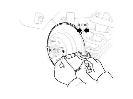
Rear brake disc runout check
| 1. |
Place a dial gauge about 5mm (0.2 in.) from the outer circumference of the brake disc, and measure the runout of the disc.
|
| 2. |
If the runout of the brake disc exceeds the limit specification, replace the disc, and then measure the runout again. |
| 3. |
If the runout exceeds the limit specification, install the brake disc after turning it 180° and then check the runout of the brake disc again. |
| 4. |
If the runout cannot be corrected by changing the position of the brake disc, replace the brake disc. |


Other information:
■ Head lamp - Type A 1. Remove the service cover clip on the wheel housing. 2. Remove the headlamp bulb cover by turning it counterclockwise. 3. Disconnect the headlamp bulb socket-connector. 4. Remove the bulb-socket from the headlamp assembly by turning the bulb-socket counterclockwise until the tabs on the bulb-socket align with the slots on the headlamp assembly.Specifications Specifications Item Specification Type Hall effect sensor Operating condition (°C)°F (-40 to 150)-40 to 302 Output voltage (V) High :1.4 Low : 0.7 Components and components location Components 1.Categories
- Manuals Home
- Kia Stinger Owners Manual
- Kia Stinger Service Manual
- New on site
- Most important about car
