
Kia Stinger CK: Fuses / Engine compartment fuse replacement
Contents:
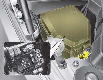
1. Turn the ignition switch and all other switches off.
2. Remove the fuse panel cover by pressing the tab and pulling the cover up. When the blade type fuse is disconnected, remove it by using the clip designed for changing fuses located in the engine compartment fuse box. Upon removal, securely insert reserve fuse of the same rating.
3. Check the removed fuse; replace it if it is blown. To remove or insert the fuse, use the fuse puller in the engine compartment fuse panel.
4. Push in a new fuse of the same rating, and make sure it fits tightly in the clips. If it fits loosely, consult an authorized Kia dealer.
CAUTION
Always securely install the fuse panel cover in the engine compartment to protect against electrical failure which may occur from water contact. Listen for the audible clicking sound to ensure fuse panel cover is securely fastened.
Multi fuse
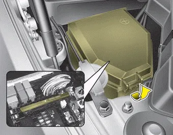
If the multi fuse is blown, it must be removed as follows:
1. Turn off the engine.
2. Disconnect the negative battery cable.
3. Remove the nuts shown in the picture above.
4. Replace the fuse with a new one of the same rating.
5. Reverse these steps to reinstall the multi fuse.
✽ NOTICE
Do not disassemble nor assemble the multi fuse when it is secured with nuts and bolts. Incorrect or partial assembly torque may cause a fire. Have the vehicle checked by an authorized Kia dealer.
Main fuse
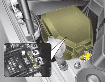
If the main fuse is blown, it must be removed as follows:
1. Turn off the engine.
2. Disconnect the negative battery cable.
3. Remove the nuts shown in the picture above.
4. Replace the fuse with a new one of the same rating.
5. Reverse these steps to reinstall the main fuse.
✽ NOTICE
The electronic system may not function correctly even when the engine compartment and internal fuse box’s individual fuses are not disconnected. In such case the cause of the problem may be disconnection of the main fuse.
Since the main fuse is designed more intricately than other parts, have the vehicle checked by an authorized Kia dealer.


Other information:
Kia Stinger (CK) 2018-2023 Owner's Manual: Shift Lever
Components and components location Components 1. Manual control lever 2. Shift cable 3. Shift lever assembly 4. Knob Repair procedures Removal 1. Shift the gear to "N". 2. Remove the knob (A) by pulling it in the direction of arrow after removing the boots from the console upper cover.Kia Stinger (CK) 2018-2023 Owner's Manual: Knee Airbag (KAB) Module
Description and operation Description Installed inside the crash pad, the knee airbag (KAB) protects the driver in the event of a frontal crash. The SRSCM determines if and when to deploy the KAB. Never attempt to measure the circuit resistance of the airbag module (squib) even if you are using a specified tester.Categories
- Manuals Home
- Kia Stinger Owners Manual
- Kia Stinger Service Manual
- New on site
- Most important about car
Contents
