Kia Stinger CK: Your vehicle at a glance
Contents:
Exterior overview
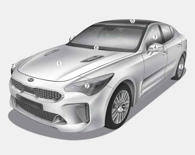
■ Front view
1. Hood
2. Head lamp (Features of your vehicle)
3. Wheel and tire (Maintenance)
4. Outside rearview mirror
5. Wide sunroof
6. Front windshield wiper blades
Front windshield wiper blades
7. Windows
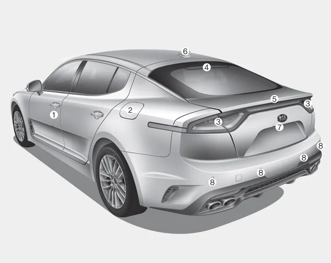
■ Rear view
1. Door
2. Fuel filler lid
3. Rear combination lamp
4. High mounted stop lamp
5. Liftgate
6. Antenna
7. Rear view monitor
8. Parking distance warning-reverse
Interior overview
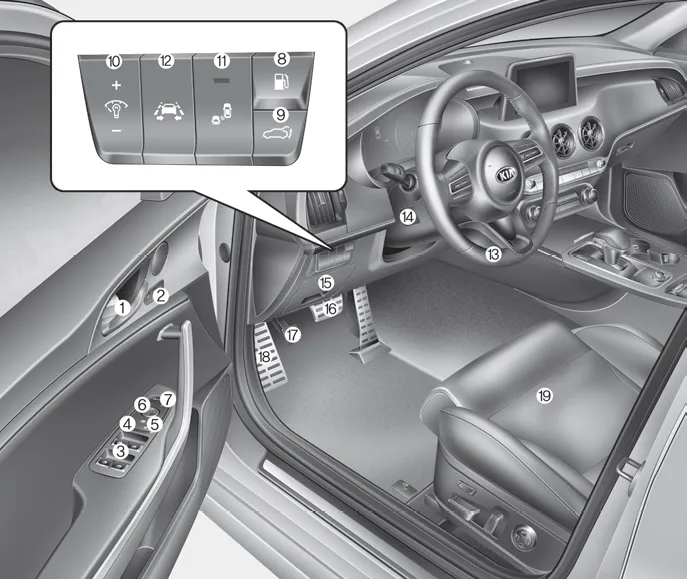
1. Door lock/unlock button
2. Driver position memory system button
3. Power window switches
4. Central door lock switch
5. Power window lock button
6. Outside rearview mirror control switch
7. Outside rearview mirror folding button
8. Fuel filler lid release button
9. Power liftgate open/close button
10. Instrument panel illumination control switch
11. BCW On/OFF button
12. Lane Keeping Assist system button
13. Steering wheel
14. Steering wheel tilt control
15. Inner fuse panel
16. Brake pedal
17. Parking brake pedal
18. Hood release lever
19. Seat
Instrument panel overview

1. Driver`s front air bag
2. Horn
3. Instrument cluster
4. Wiper/Washer
5. Engine start/stop button
6. Cruise control
7. Hazard warning flasher switch
8. Climate control system
9. Shift lever
10. Heated steering wheel button
11. ISG (Idle stop and go) system button
12. 360° camera monitoring system
13. Seat warmer
14. Electronic parking brake(EPB) switch
15. AUTO HOLD control button
16. Center console box
17. USB charger
18. Glove box
19. Passenger`s front air bag
20. Power outlet
21. Drive mode control knob
22. Electronic stability control button
Engine compartment
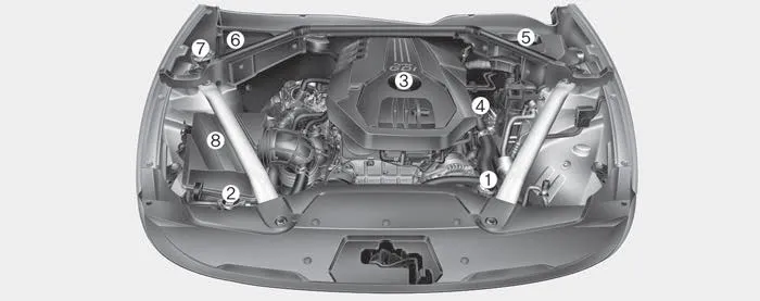
■ THETA II 2.0L T-GDI Engine (Gasoline)

■ Lambda II PE 3.3L T-GDI Engine (Gasoline)
1. Engine coolant reservoir
2. Radiator cap
3. Engine oil filler cap
4. Engine oil dipstick
5. Brake fluid reservoir
6. Fuse box
7. Windshield washer fluid reservoir
8. Air cleaner


Other information:
Kia Stinger (CK) 2018-2023 Owner's Manual: Body Electrical System
General information General Troubleshooting Information Before Troubleshooting 1. Check applicable fuses in the appropriate fuse/relay box. 2. Check the battery for damage, state of charge, cleanliness and tight connections. D 2.2 R VGT (Refer to Engine Electrical System - "Charging System") G 2.Components and components location Components [Mobis] Connector Pin Information No. Connector A Connector B 1 Battery (+) Rear door left speaker (+) 2 Battery (+) Rear door left speaker (-) 3 Battery (+) Rear door right speaker (+) 4 Battery (+) Rear door right sCategories
- Manuals Home
- Kia Stinger Owners Manual
- Kia Stinger Service Manual
- New on site
- Most important about car
Contents
