Kia Stinger CK: Audio / External AMP
Components and components location
| Components |
| [Mobis] |
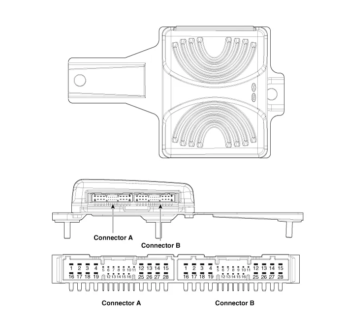
Connector Pin Information
|
No. |
Connector A |
Connector B |
|
1 |
Battery (+) |
Rear door left speaker (+) |
|
2 |
Battery (+) |
Rear door left speaker (-) |
|
3 |
Battery (+) |
Rear door right speaker (+) |
|
4 |
Battery (+) |
Rear door right speaker (-) |
|
5 |
⁻ |
⁻ |
|
6 |
Multimedia-CAN (High) |
⁻ |
|
7 |
Multimedia-CAN (Low) |
⁻ |
|
8 |
ACC |
⁻ |
|
9 |
Navigation voice (+) |
⁻ |
|
10 |
⁻ |
⁻ |
|
11 |
⁻ |
⁻ |
|
12 |
Front door left speaker (+) |
⁻ |
|
13 |
Front door left speaker (-) |
⁻ |
|
14 |
Front door left speaker (+) |
⁻ |
|
15 |
Front door left speaker (-) |
⁻ |
|
16 |
Ground |
Sub woofer speaker 1 (+) |
|
17 |
Ground |
Sub woofer speaker 1 (-) |
|
18 |
Ground |
Sub woofer speaker 2 (+) |
|
19 |
Ground |
Sub woofer speaker 2 (-) |
|
20 |
SPDIF (+) |
⁻ |
|
21 |
SPDIF (-) |
⁻ |
|
22 |
SPDIF (Ground) |
⁻ |
|
23 |
Navigation voice (-) |
⁻ |
|
24 |
IGN1 |
⁻ |
|
25 |
Crash pad center speaker (+) |
⁻ |
|
26 |
Crash pad center speaker (-) |
⁻ |
|
27 |
⁻ |
⁻ |
|
28 |
⁻ |
⁻ |
Repair procedures
| Removal |
| 1. |
Disconnect the negative (-) battery terminal. |
| 2. |
Remove the luggage side trim [RH]. (Refer to Body - "Luggage Side Trim") |
| 3. |
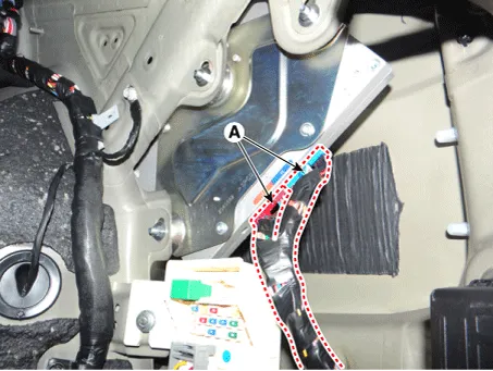
Disconnect the external amplifier connectors (A).
|
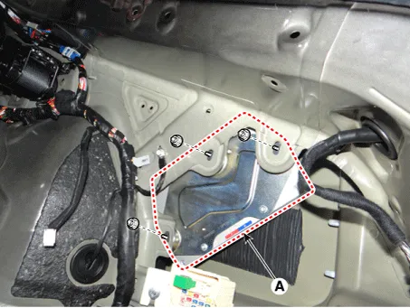
| 4. |
Remove the external amplifier (A) after loosening the mounting nuts.
|
| Installation |
| 1. |
Install the external amplifier after connecting the connectors. |
| 2. |
Install the luggage side trim [RH]. |
| 3. |
Connect the negative (-) battery terminal.
|

| Inspection |
|
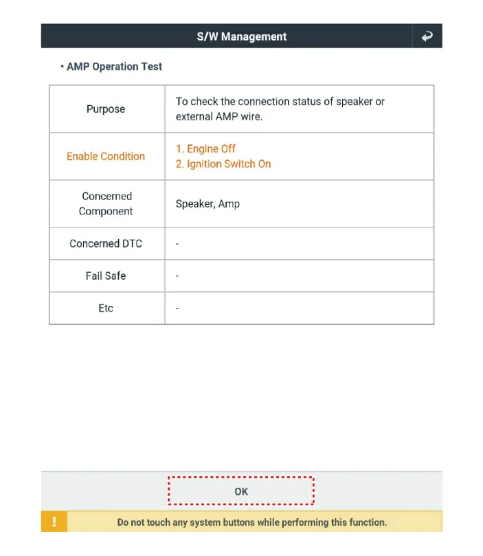
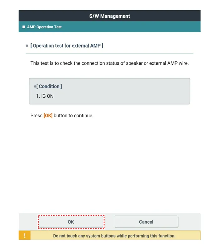
| 1. |
In the body electrical system, failure can be quickly diagnosed by using the vehicle diagnostic system (KDS). The diagnostic system (KDS) provides the following information.
|
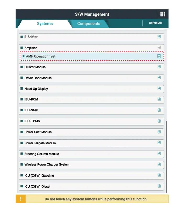
| 2. |
Select the 'Car model' and the system to be checked in order to check the vehicle with the tester. |
| 3. |
Select the 'Amplifier' to check the Audio. |
| 4. |
Select the 'Current data" menu to search the current state of the input/output data. The input/output data for the sensors corresponding to the Audio can be checked.
|


Other information:
Kia Stinger (CK) 2018-2023 Service Manual: Brake System
Repair procedures Operation and Leakage Check Check all of the following items: Component Procedure Brake Booster (A) Check brake operation by applying the brakes during a test drive. If the brakes do not work properly, check the brake booster. Replace the brake booster as an assembly if it does not work properly or if there are signs of leakage.Kia Stinger (CK) 2018-2023 Service Manual: Balance Shaft & Oil Pump
Repair procedures Removal BSM (Balance Shaft Module) Chain System 1. Remove the timing chain. (Refer to Timing System - "Timing Chain") 2. Install a stopper pin (A) after compressing the balance shaft chain tensioner. 3. Remove the balance shaft chain tensioner (B).Categories
- Manuals Home
- Kia Stinger Owners Manual
- Kia Stinger Service Manual
- New on site
- Most important about car
