Kia Stinger CK: Audio / Antenna
Components and components location
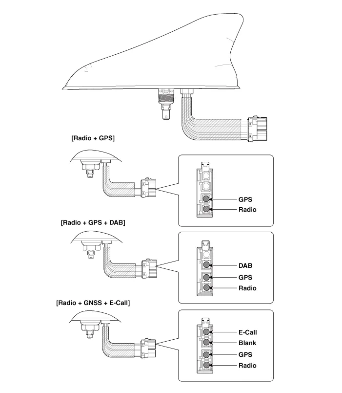
| Components |
Schematic diagrams
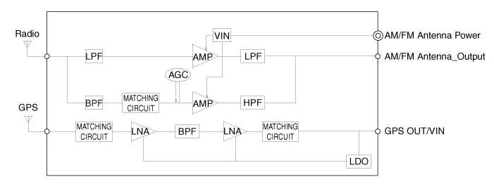
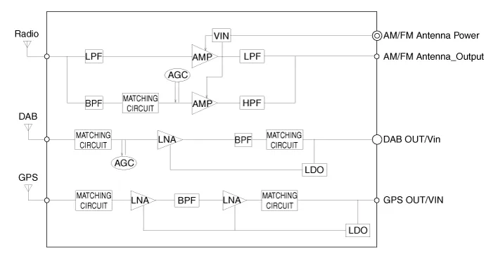
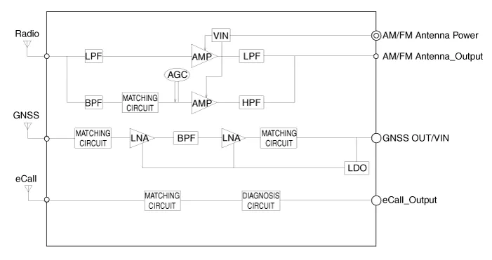
| Circuit Diagram |
[Radio + GPS]
[Radio + GPS + DAB]
[Radio + GNSS + E-Call]
Repair procedures
| Removal |
Roof antenna
| 1. |
Disconnect the negative (-) battery terminal. |
| 2. |
Remove the roof trim assembly. (Refer to Body - "Roof Trim Assembly") |
| 3. |
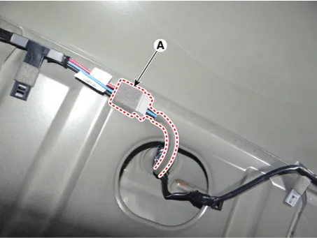
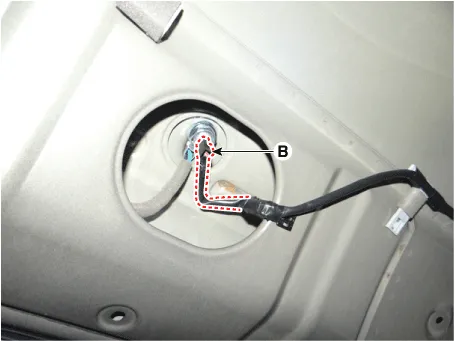
Disconnect the roof antenna main connector (A) and roof antenna power connector (B).
|
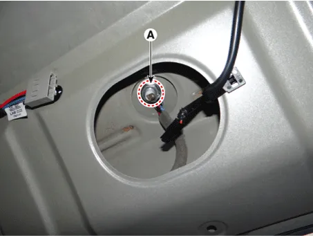
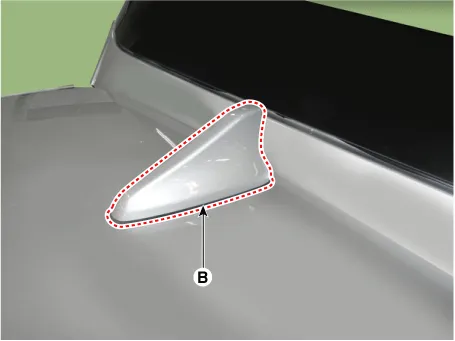
| 4. |
Remove the roof antenna (B) after loosening a nut (A).
|
| Installation |
Roof anenna
| 1. |
Install the roof antenna. |
| 2. |
Connect the roof antenna main connector and roof antenna power connecter. |
| 3. |
Install the roof trim assembly. |
| 4. |
Connect the negative (-) battery terminal.
|

| Inspection |
Antenna Cable
| 1. |
Check for continuity between the center poles of antenna cable.
|
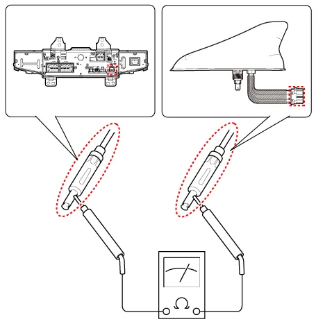
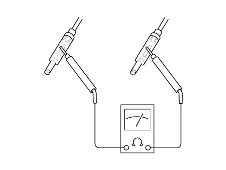
| 2. |
Check for continuity between the outer poles of antenna cable. There should be continuity.
|
| 3. |
If there is no continuity, replace the antenna cable. |
| 4. |
Check for continuity between the center pole (A) and outer pole (B) of antenna cable. There should be no continuity.
|
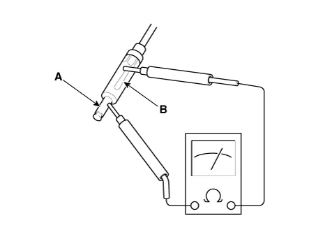
| 5. |
If there is continuity, replace the antenna cable. |


Other information:
Kia Stinger (CK) 2018-2023 Service Manual: Hood Latch Release Handle
Components and components location Component Location 1. Hood latch release handle Repair procedures Replacement 1. After loosening the mounting screw, remove the hood latch release handle (A). 2. Install in the reverse order of removal.Kia Stinger (CK) 2018-2023 Service Manual: Parking Distance Warning (PDW) Switch
Components and components location Components Schematic diagrams Circuit Diagram Repair procedures Removal Put on gloves to protect your hands. • When prying with a flat-tip screwdriver or use a prying trim tool, wrap it with protective tape, and apply protective tape around the related parts, to prevent damage.Categories
- Manuals Home
- Kia Stinger Owners Manual
- Kia Stinger Service Manual
- New on site
- Most important about car
