Kia Stinger CK: Audio / Audio Remote Control
Components and components location
| Components |
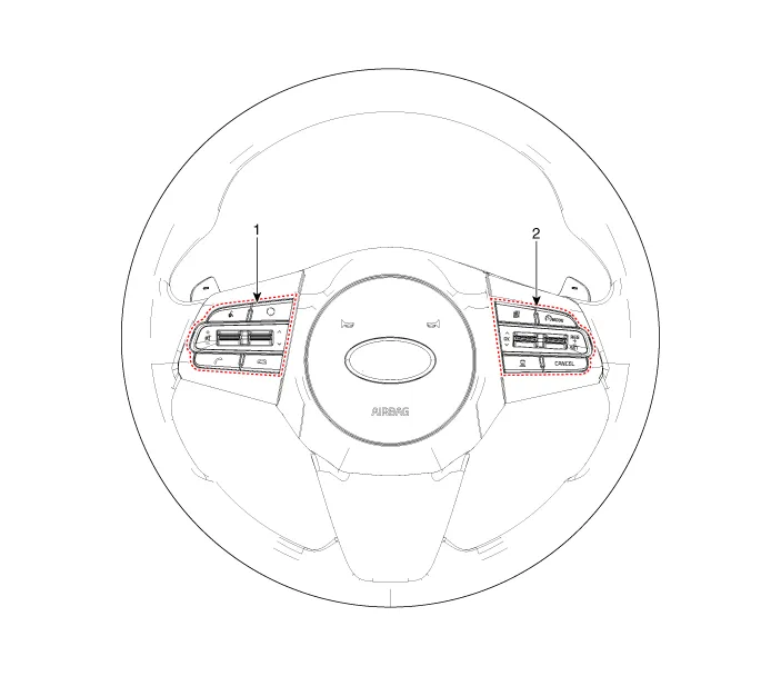
| 1. Left Remote Control Switch
(Audio + Bluetooth + Voice) |
2. Right Remote Control Switch
(Trip Computer + ACC + SCC) |
Schematic diagrams
| Circuit Diagram |
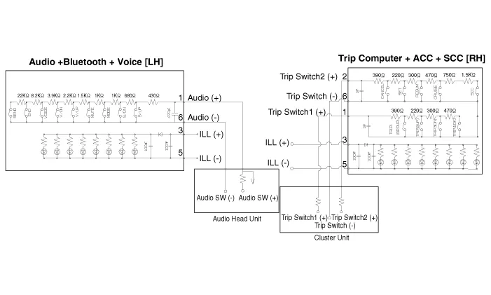
| [Audio + Bluetooth + Voice] |
| [Trip + ACC] |

| [Trip + ACC + SCC] |
Repair procedures
| Removal |
| 1. |
Disconnect the negative (-) battery terminal. |
| 2. |
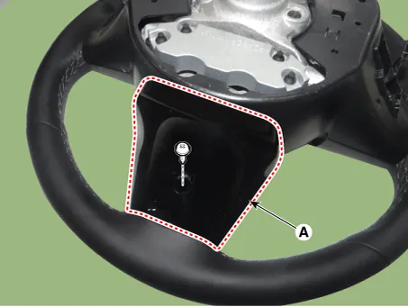
Remove the steering wheel assembly. (Refer to Steering System - "Steering Wheel") |
| 3. |
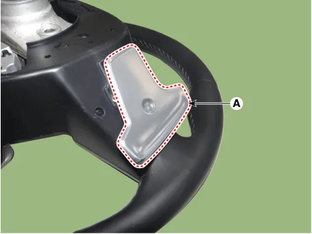
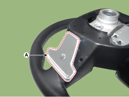
Remove the paddle shift switch (A) after loosening the mounting screws. [LH]
[RH]
|


| 4. |
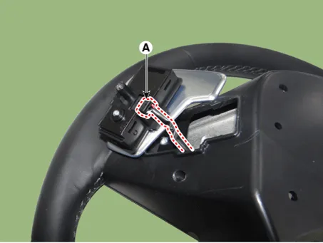
Disconnect the paddle shift switch connector (A). [LH]
[RH]
|

| 5. |
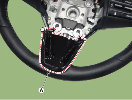
Remove the steering front cover (A) after loosening the mounting screws.
|
| 6. |
Remove the steering rear cover (A) after loosening the mounting screws.
|
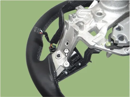
| 7. |
Remove the steering back cover (A) after loosening the mounting screws.
|

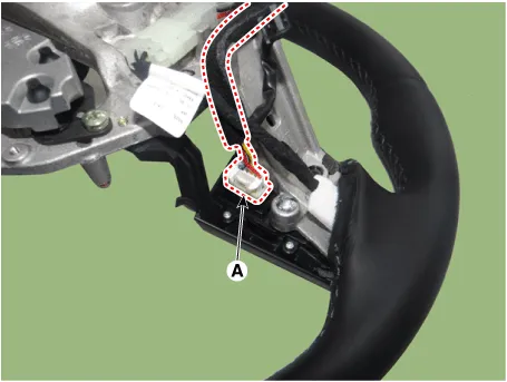
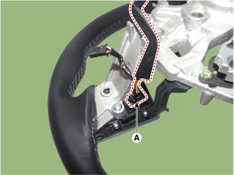
| 8. |
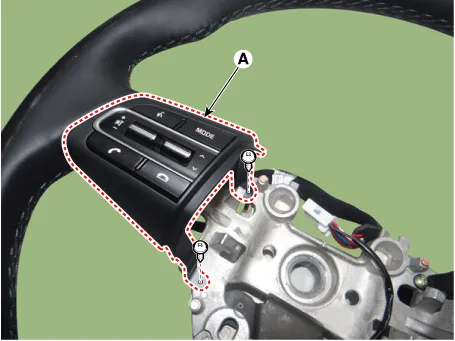
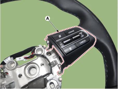
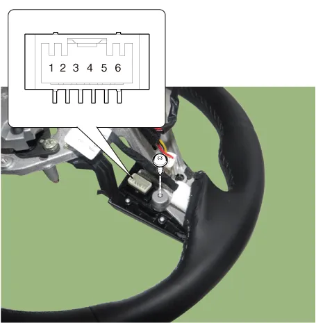
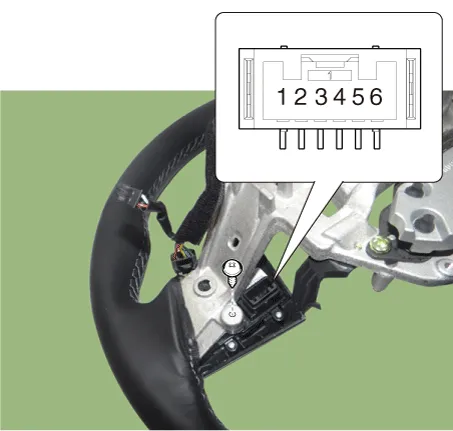
Disconnect the steering wheel remote control connector (A). [LH]
[RH]
|
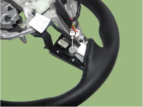
| 9. |
Remove the steering wheel remote control (A) after loosening the mounting screws. [LH]
[RH]
|
| Installation |
| 1. |
Install the steering wheel remote control. |
| 2. |
Connect the steering remote control connector. |
| 3. |
Install the steering back cover. |
| 4. |
Install the steering rear cover. |
| 5. |
Install the steering front cover. |
| 6. |
Connect the paddle shift switch connector. |
| 7. |
Install the paddle shift switch. |
| 8. |
Install the steering wheel assembly. |
| 9. |
Connect the negative (-) battery terminal. |
| Inspection |
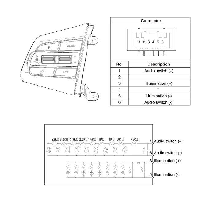
| 1. |
Check for resistance between terminals in each switch position (LH).
[LH : Audio + Bluetooth + Voice]
|
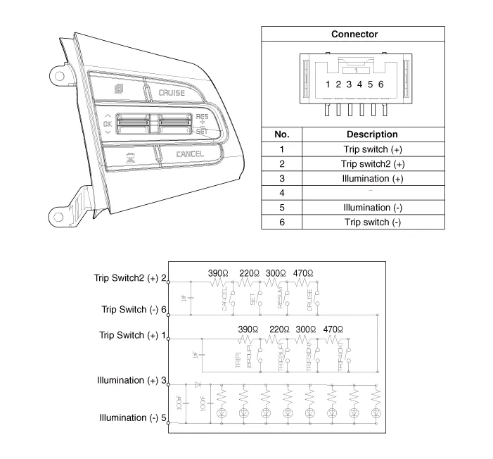
| 2. |
Check for resistance between terminals in each switch position (RH).
[RH : Trip + ACC + SCC]
|


Other information:
Kia Stinger (CK) 2018-2023 Service Manual: Headlamp Leveling Actuator
Components and components location Circuit Diagram Repair procedures Removal 1. Disconnect the negative (-) battery terminal. 2. Remove the headlamp assembly. (Refer to Lighting System - "Headlamps") Installation 1. Install the headlamp assembly.Kia Stinger (CK) 2018-2023 Service Manual: Vehicle recognition
Some vehicles ahead in your lane cannot be recognized by the sensor as follows: - Narrow vehicles such as motorcycles or bicycles - Vehicles offset to one side - Slow-moving vehicles or suddendecelerating vehicles - Stopped vehicles - Vehicles with small rear profiles such as trailers with no loads A vehicle ahead cannot be recognized correctly by the sensor if any of following occurs: - When the vehicle is pointing upwards due to overloading in the trunk or luggage area.Categories
- Manuals Home
- Kia Stinger Owners Manual
- Kia Stinger Service Manual
- New on site
- Most important about car
