
Kia Stinger CK: Audio / Multimedia Jack
Schematic diagrams
| Circuit Diagram |
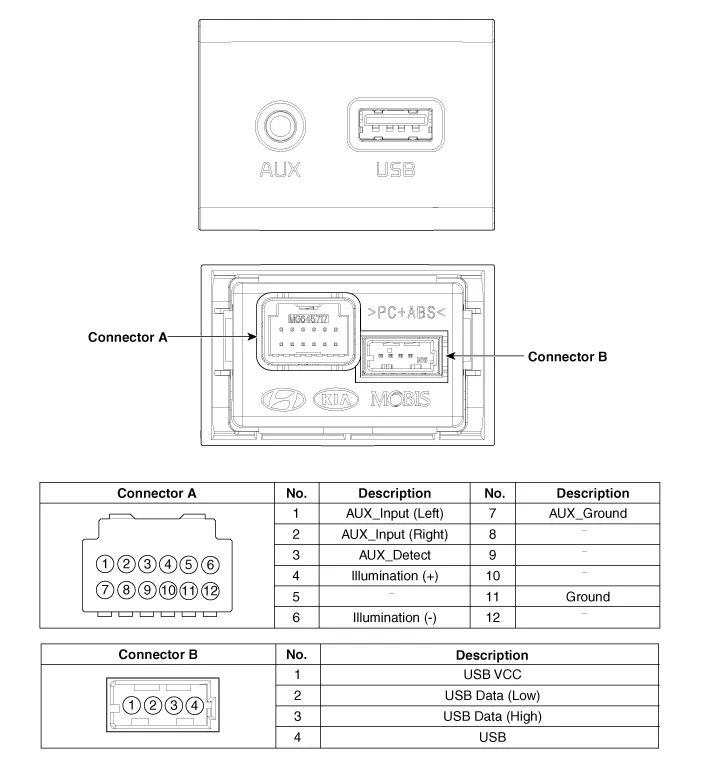
Description and operation
| Description |
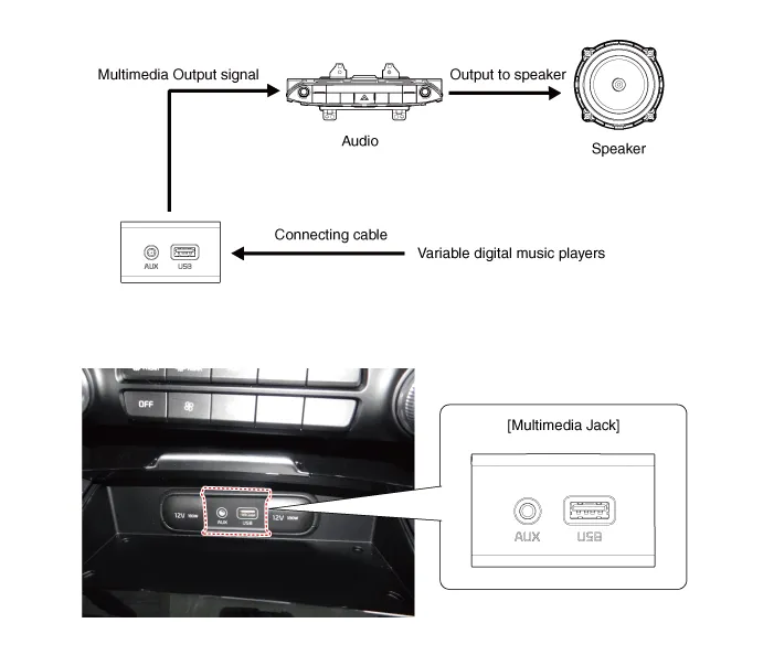
The multimedia jack on the console upper cover is for customers who like to listen to external portable music players like the MP3 etc., through the vehicle's sound system when it is linked to this jack. The customer has this added option.
In case of distorted sound coming from the AUX-linked external music players, the audio unit may not be defective but the output level of the player does not match the specification of the AUX.
Repair procedures
| Removal |
Multimedia Jack
Put on gloves to protect your hands. |

|

| 1. |
Disconnect the negative (-) battery terminal. |
| 2. |
Remove the console complete assembly. (Refer to Body - "Floor Console Assembly") |
| 3. |
Remove the front cover (A) after loosening the mounting screws.
|

| 4. |
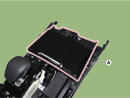
Remove the floor console tray (A).
|
| 5. |
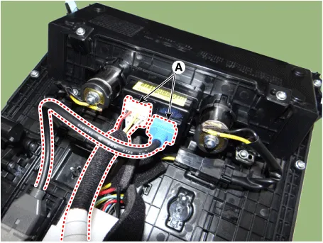
Disconnect the multimedia jack connectors (A).
|
| 6. |
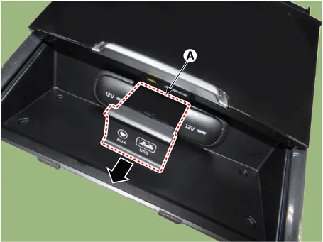
Remove the multimedia jack (A) after releasing the fixed hooks.
|

USB Charger
| 1. |
Disconnect the negative (-) battery terminal. |
| 2. |
Remove the rear console cover. (Refer to Body - "Rear Console Cover") |
| 3. |
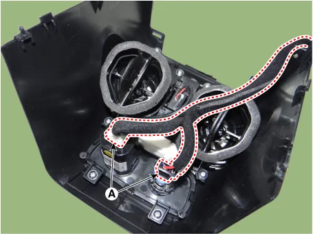
Disconnect the USB charger connector (A).
|
| 4. |
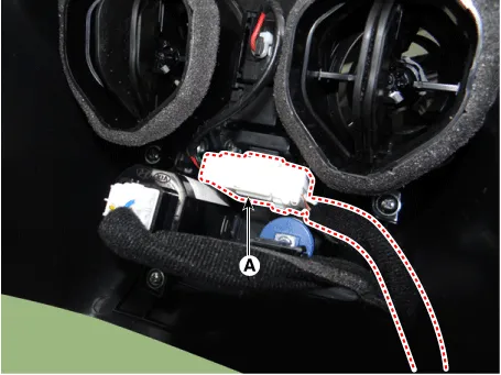
Disconnect the rear heater&A/C control unit connector (A).
|
| 5. |
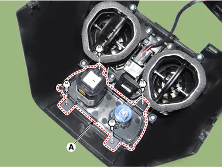
Remove the USB charger (A) after loosening the mounting screws.
|
| Installation |
Multimedia Jack
| 1. |
Install the multimedia jack. |
| 2. |
Connect the multimedia jack connector. |
| 3. |
Install the floor console tray. |
| 4. |
Install the front cover. |
| 5. |
Install the console complete assembly. |
| 6. |
Connect the negative (-) battery terminal. |
USB Charger
| 1. |
Install the USB charger. |
| 2. |
Connect the rear heater&A/C control unit connector. |
| 3. |
Connect the USB charger connector. |
| 4. |
Install the rear console cover. |
| 5. |
Connect the negative (-) battery terminal. |


Other information:
Kia Stinger (CK) 2018-2023 Service Manual: Around View Monitor (AVM) Unit
Components and components location Components Schematic diagrams Circuit Diagram Repair procedures Removal Put on gloves to protect your hands. • When prying with a flat-tip screwdriver or use a prying trim tool, wrap it with protective tape, and apply protective tape around the related parts, to prevent damage.Description and operation Description BI-FUNCTION 1. Definition – A headlamp with integrated functions of high and low beam – The light is controlled by rotating the shield inserted to the lens. (A solenoid is adopted.) [Halogen Type] [LED Type] 2.Categories
- Manuals Home
- Kia Stinger Owners Manual
- Kia Stinger Service Manual
- New on site
- Most important about car
