Kia Stinger CK: Ignition System / Ignition Coil
Description and operation
| Description |
An ignition coil is an induction coil in an engine's ignition system which transforms the battery's low voltage to the high voltage needed to create an electric spark in the spark plugs to ignite the fuel. Coils have an internal resistor while others rely on a resistor wire or an external resistor to limit the current flowing into the coil from the battery 12 V supply.
Schematic diagrams
| Circuit Diagram |
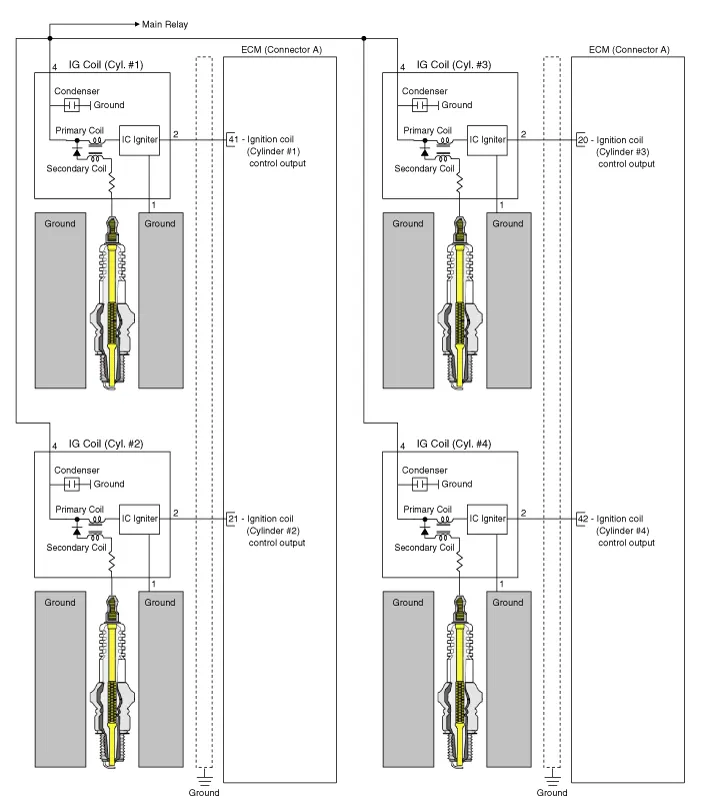
| Connector View |
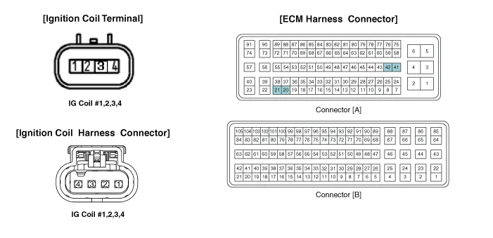
| Ignition Coil Terminal Function |
Ignition Coil (Cylinder #1)
|
Pin No. |
Description |
Connected to |
|
1 |
Ground |
Chassis |
|
2 |
ignition Coil #1 Control output |
ECM Connector A (41) |
|
3 |
- |
|
|
4 |
Battery power (B+) |
Main Relay |
Ignition Coil (Cylinder #2)
|
Pin No. |
Description |
Connected to |
|
1 |
Ground |
Chassis |
|
2 |
ignition Coil #2 Control output |
ECM Connector A (21) |
|
3 |
- |
|
|
4 |
Battery power (B+) |
Main Relay |
Ignition Coil (Cylinder #3)
|
Pin No. |
Description |
Connected to |
|
1 |
Ground |
Chassis |
|
2 |
ignition Coil #3 Control output |
ECM Connector A (20) |
|
3 |
- |
|
|
4 |
Battery power (B+) |
Main Relay |
Ignition Coil (Cylinder #4)
|
Pin No. |
Description |
Connected to |
|
1 |
Ground |
Chassis |
|
2 |
ignition Coil #4 Control output |
ECM Connector A (42) |
|
3 |
- |
|
|
4 |
Battery power (B+) |
Main Relay |
Repair procedures
| Removal |
| 1. |
Switch "OFF" the ignition and disconnect the negative (-) battery terminal. |
| 2. |
Remove the engine cover. (Refer to Engine Mechanical System - "Engine Cover") |
| 3. |
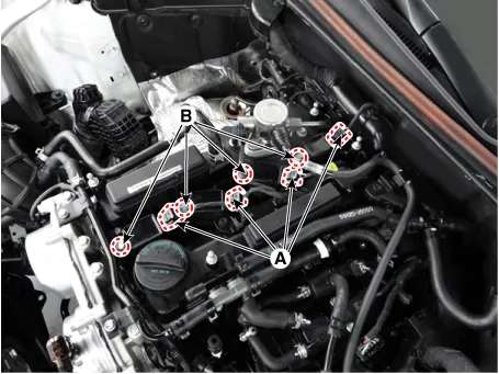
Disconnect the ignition coil connector (A). |
| 4. |
Remove the ignition coil after loosening the mounting bolt (B).
|
| Installation |
| 1. |
Install in the reverse order of removal.
|


Other information:
Kia Stinger (CK) 2018-2023 Service Manual: Engine oil
Checking the engine oil level ■ THETA II 2.0L T-GDI Engine (Gasoline) ■ Lambda II PE 3.3L T-GDI Engine (Gasoline) 1. Be sure the vehicle is on level ground. 2. Start the engine and allow it to reach normal operating temperature. 3. Turn the engine off and wait for a few minutes (about 5 minutes) for the oil to return to the oil pan.Kia Stinger (CK) 2018-2023 Service Manual: Glove Box Housing
Components and components location Component Location 1. Glove box housing Repair procedures Replacement Put on gloves to protect your hands. • Use a plastic panel removal tool to remove interior trim pieces without marring the surface.Categories
- Manuals Home
- Kia Stinger Owners Manual
- Kia Stinger Service Manual
- New on site
- Most important about car
