Kia Stinger CK: Integrated Memory Seat (IMS) System / Integrated Memory Seat (IMS) Unit
Kia Stinger (CK) 2018-2023 Service Manual / Body Electrical System / Integrated Memory Seat (IMS) System / Integrated Memory Seat (IMS) Unit
Components and components location
| Components |
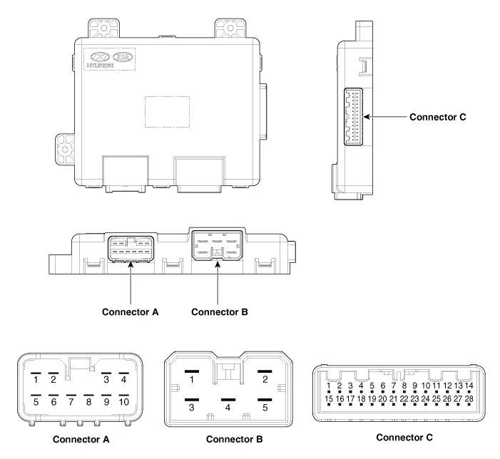
Connector Pin Information
|
No |
Connector A |
Connector B |
Connector C |
|
1 |
Cushion extension motor (Front) |
Battery (+) |
Slide switch (Front) |
|
2 |
Recline motor (Front) |
Ground |
Recline switch (Front) |
|
3 |
Rear height motor (Up) |
Battery (+) |
Frout tilt switch (Up) |
|
4 |
Slide motor (Front) |
- |
Rear height switch (Up) |
|
5 |
Cushion extension motor (Rear) |
Ground |
Cushion extension switch (Front) |
|
6 |
Recline motor (Rear) |
|
B-CAN (High) |
|
7 |
Front tilt motor (Up) |
B-CAN (Low) |
|
|
8 |
Front tilt motor (Down) |
- |
|
|
9 |
Rear height motor (Down) |
- |
|
|
10 |
Slide motor (Rear) |
Slide hall sensor |
|
|
11 |
|
Front tilt hall sensor |
|
|
12 |
- |
||
|
13 |
Seat position sensor power |
||
|
14 |
IGN1 |
||
|
15 |
Slide switch (Rear) |
||
|
16 |
Recline switch (Rear) |
||
|
17 |
Front tilt switch (Down) |
||
|
18 |
Rear height switch (Down) |
||
|
19 |
Cushion extension switch (Rear) |
||
|
20 |
Ground |
||
|
21 |
- |
||
|
22 |
- |
||
|
23 |
- |
||
|
24 |
Recline hall sensor |
||
|
25 |
Rear height hall sensor |
||
|
26 |
Cushion extension hall sensor |
||
|
27 |
- |
||
|
28 |
Battery (+) |
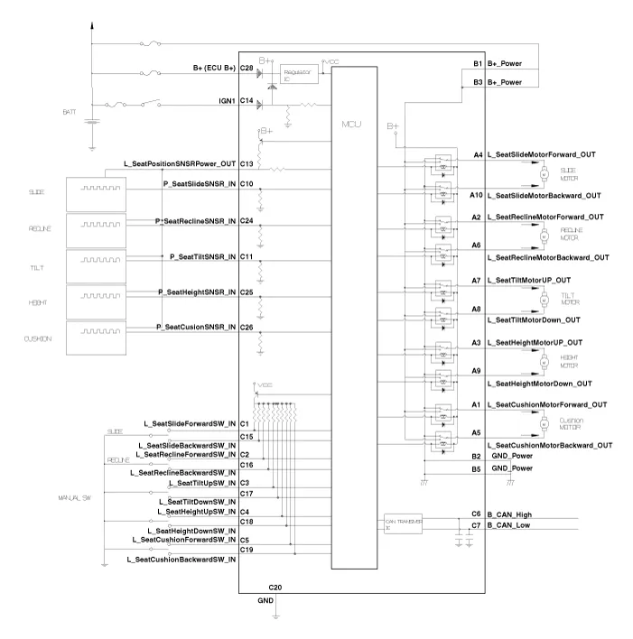
Schematic diagrams
| Circuit Diagram |
Repair procedures
| Removal |
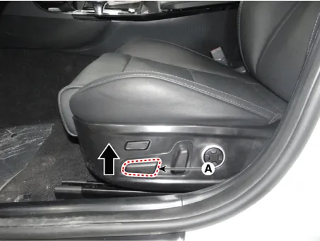
| 1. |
Before removing the driver side seat assembly, pull it upward to the maximum by pushing the front seat height adjusting switch (A).
|
| 2. |
Disconnect the negative (-) battery terminal |
| 3. |
Remove the driver front seat assembly. (Refer to Body - "Front Seat Assembly") |
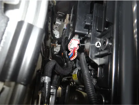
| 4. |
Disconnect the integrated memory seat unit connectors (A).
|
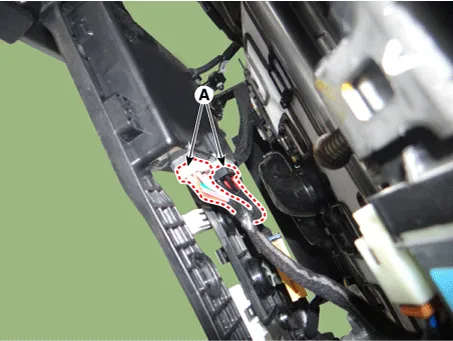
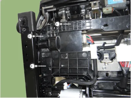
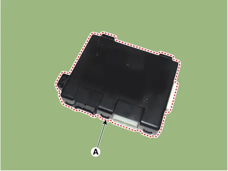
| 5. |
Remove the integrated memory seat unit (A) after loosening the mounting screws.
|
| Installation |
| 1. |
Install the integrated memory seat unit. |
| 2. |
Connect the integrated memory seat unit connectors. |
| 3. |
Install the driver front seat assembly. |
| 4. |
Connect the negative (-) battery terminal. |
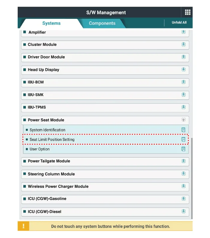
| 5. |
Perform the seat limit position setting using the KDS.
|


Other information:
Kia Stinger (CK) 2018-2023 Service Manual: ISG (Idle Stop and Go) system
Your vehicle may be equipped with the ISG system, which reduces fuel consumption by automatically shutting down the engine, when the vehicle is at a standstill. (For example : red light, stop sign and traffic jam) The engine starts automatically as soon as the starting conditions are met. The ISG system is ON whenever the engine is running. ✽ NOTICE When the engine automatically starts by the ISG system, some warning lights (ABS, ESC, ESC OFF, EPS or Parking brake warning light) may turn on for a few seconds.Description and operation Description Electric E-CVVT system is electric continuous variable valve timing system. It is located on the intake camshaft of the engine and uses motor rotation to control the rotation angle of camshaft relative to the rotation of crankshaft regardless of engine pressure. E-CVVT controls the DC motor current (duty signal) to more closely control the system compared to the previous pressure type, to increase reaction speed of cam, to improve startability, and to reduce the emission of exhaust gas.Categories
- Manuals Home
- Kia Stinger Owners Manual
- Kia Stinger Service Manual
- New on site
- Most important about car

Copyright © 2026 www.kstinger.com 0.0099